Power supply tested…
 That’s 8,950 volts!
Finally got to the testing phase of my power supply design. The smoke test was successful (in that there was no smoke) and the max voltage reading was close to 9000 volts negative, which means the power supply is working as designed.
This power supply converts normal house AC voltage to something that can generate fusion in the reactor. The power can be varied from zero to maximum voltage by using a component called a variable transformer. The variable transformer takes input from the wall socket and outputs to a box that steps the voltage way up and turns it into DC current. The box looks relatively simple, shown below:
 Looking down, the box contains a blue neon sign transformer on the right. This is the thing that steps up the voltage way up. On the left you can just make out some high voltage microwave diodes that look like little black rectangles. Just to the right of the transformer is a gold colored high power shunt resistor for measuring current. The cylindrical object in the upper left corner of the pic is the variable transformer. The diodes rectify the AC signal, meaning they turn AC into DC. Diodes allow current to flow one direction and not in the reverse direction. If you design the circuit correctly, you end up with a high voltage negative DC supply, exactly what you want to produce fusion.
Believe it or not, this circuit is extremely simple and easy to understand and make for those with the most basic knowledge of electronics. What makes this device unique is the extreme high voltage. This is not an every-day home electronics project, these voltages can be instantly lethal if not managed correctly. Just about every aspect of this device has to be designed with that in mind if you want to maintain a safety factor.
The first design rule is to have no exposed high voltage that could be touched by accident. To do this I needed to come up with an enclosure, but even this isn’t as simple as it sounds. You need a material that can insulate and won’t break down in a high voltage environment. This is what I mean: Air is an insulator. That’s why you can walk near a wall socket and not get electrocuted. But if there is a big enough voltage difference, air “breaks down” and becomes a conductor, for example, lightning. As a matter of fact, air is not one of the better high voltage insulators, it can break down in as little as 20,000 volts per inch. That sounds like a lot of voltage but note that my power supply is nearly 9000 volts, meaning that it could arc across a little less than a half inch of air. This means just getting close to the supply without touching it could cause electrocution.
 Wood and rubber are not good insulators for these high voltages. However, it turns out that polyvinyl chloride, or PVC, is an excellent insulator with a high dielectric breakdown. So I constructed a supply enclosure by epoxy-ing together PVC junction boxes I bought at a home improvement store. I then cut and drilled to accommodate the transformer and other components. As you can see in the pic at left, the wiring internal to the box is bare. This is intentional as ordinary wire insulation is inappropriate at high voltages, it can potentially break down and catch fire at these voltages. As long as it is enclosed during operation, there is no danger of electrocution and the wire layout is intended to prevent arcing between components.
The (poor quality) pic on the right shows one half of the rectifier, two high voltage microwave diodes wired in series to screw terminals on PVC standoffs that I epoxied to the case. The standoffs provide a base for the screw terminal without having to drill through the case. The dark blue streaks you see in the photos is the color of the epoxy. The two diodes on the right are half of the rectifier, there are two more wired to the other side of the transformer. Normally it only takes two diodes to make a full-wave rectifier, but again because of the very high voltages being generated, you need a special setup to prevent the diodes from failing. These are 12,000 volt rated microwave oven diodes, placing them in series gives you a 24,000 volt “rating” that give you an operating margin for safety. Finally, the diodes must be arranged so that they produce a DC current that is negative with respect to ground. This “negative hot” quality is necessary for this type of reactor design.
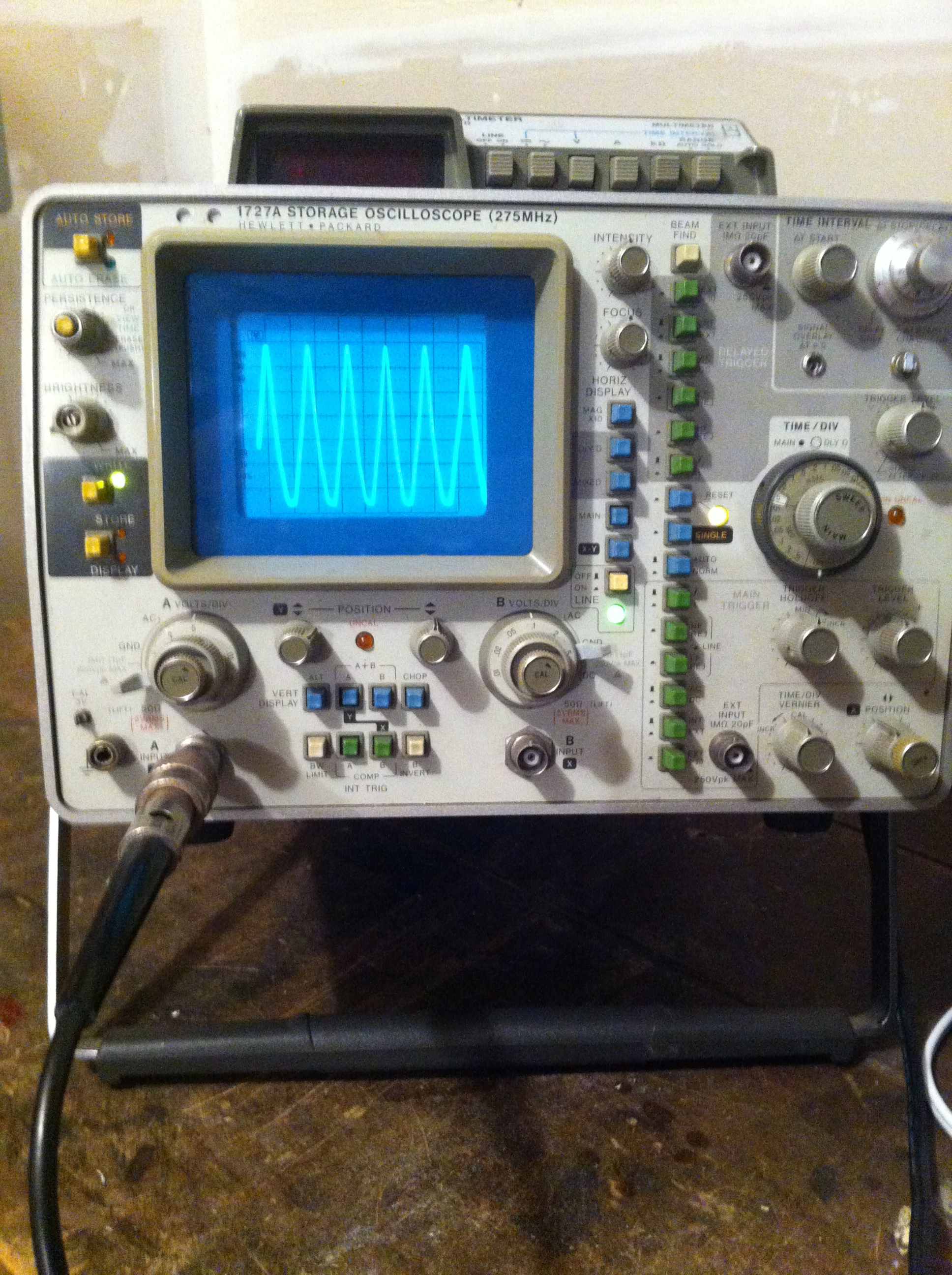
The final pic at the bottom is an oscilloscope trace of the output showing “full wave” rectification. Zero volts is at the top of the screen, meaning the wave is entirely negative volts DC. It is not showing the full power output but a lower voltage representative wave because I don’t have an appropriate probe for my scope to measure more than 200 volts input. Note that because this is a wave, the voltmeter pic at the top of this posting is what is called a “root-mean-square” of the wave, the actual peak voltage at full power is closer to 11,000 volts!
Also of note, the wave is DC, that is, it does not reverse direction though there is an amazing amount of ripple. This could be smoothed out with a giant capacitor but I’m hoping I won’t need one, at least for this stage of the project.
Posted in Nuclear Fusion Reactor by Mark with comments disabled.