Shortwave Radio Antennas
Ok, this is a long post about diagnosing and fixing a shortwave radio antenna on our sailboat Good Karma. Not interesting for those who are not into technical detail.
On most bluewater sailing vessels there is a shortwave radio for communication, usually called an “SSB radio.” One thing every radio needs is a good antenna. On most sailboats, the antenna is the backstay of the mast, the cable that holds the main mast to the back of the boat. It’s a good choice because it’s basically a long wire that can be insulated easily (necessary for an antenna).
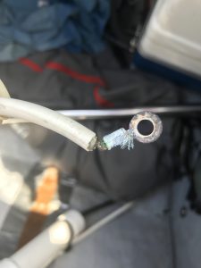
My radio could transmit and receive email and I was happy with it until I notice that the connection from the radio to the backstay was getting frayed (below). I was also having great difficulty with voice transmission to stations that should have been receiving me with no problem.
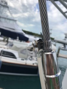
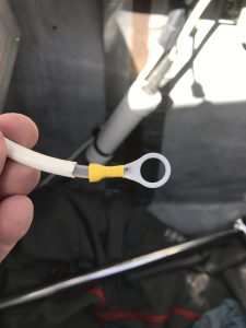
The antenna feed (white wire on left) was connected via an unprotected hose clamp to the backstay. The problem was this is exposed to the elements (water and salt air), not to mention the not-so-great mechanical connector that doesn’t protect against breakage of wire. At Spanish Wells I bought some new hardware (below):
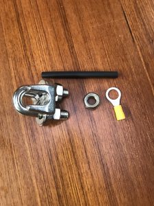
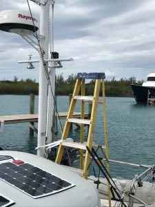
Left to right: A cable clamp, a nut and a ring connector. The clamp would give me a solid connection to the backstay and the nut and ring connectors would grant a smooth mechanical connection between the antenna feed and backstay. The connection point needed to be about 8 feet off the deck and so I needed a ladder. I borrowed one from the marina but because of the tight space on the deck I could not deploy it completely, so I had to set it up with straps on each side to stabilize it, below:
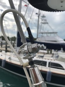
I assembled a great backstay connection and insulated the connector from the elements with electrical tape, shown below:
Everything looked great but the radio happened to work worse than before! I didn’t get it and puzzled over this problem for days. I finally decided I needed to look at the other end of the antenna feed cable, which I had to move to get the backstay connection finished. That was it! Below is what the connector to the radio looked like, corroded and almost broken:
I replaced this connector as shown below:
The result was, so far, fantastic. I’m able to contact much more distant stations. The testing isn’t complete without a voice test but I’m optimistic.
Posted in Electronics and Radios, Hacking!, Sailing by Mark with comments disabled.
Life in Vero Beach, Part I

View From Our “Back Porch”
It’s December 23rd, the temperature today was 78F, only a minor breeze, sunny and no rain. Vero Beach is nearly paradise. “Bad” weather here means it’s more windy than expected. It can get a bit chilly at night, but Colorado natives will be in shorts and sandals being asked if they are cold. No, why, is it cold? I didn’t notice.
We’ve been resting, working on the boat, running, walking, drinking, eating, and meeting many new cruisers. Nearly 100% of them are taking a break here prior to crossing over to the Bahamas, as are we.

Man O’ War Sans Tentacles
Today, Shelly was walking on the beach and came across a Portuguese Man O’ War, a stinging jellyfish. Jellyfish are my aquatic enemies. Some people don’t like snakes. Some don’t like spiders. I don’t like jellyfish. Well, if you read the link the Man O’ War isn’t a jellyfish, but a siphonophore. Fine. Don’t bring me any jellyfish or siphonophores that look and act like jellyfish.

L to R: Jack, Marie, Shelly and I at the Beach
Been hanging out with Jack and Marie, our Boulder friends and now Vero Beach friends. They are here for the winter, as they were last year. The nickname for this town is “Velcro Beach” due to the fact that many visitors stick here eventually. I understand why. Nice weather, cultural and outdoor activities, and not the least, happy people. Everyone greets you on the street here (unless they are tourists, who are obvious). Shelly pointed out that lots of people are retired and of course they’re happy. Well, I’ve seen many unhappy retired people but not here.
One of the big projects completed so far is the installation of a wifi booster. This allows us to log on to the local wifi access point from way out on our boat. Works fantastically, I am actually very impressed with the performance.
Why does it work so well? If you’re on your mobile device or your PC, you may see a remote wifi point but not actually be able to talk to it because you device doesn’t have enough oomph to talk back. Maybe you can get a connection but it’s slow and intermittent. This is because you are too far from the wifi access point. Wifi is meant to be a very short range radio connection, not intended to travel over a quarter mile.
The booster not only brings the signal to you but also transmits at higher power so the access point can see you. Generally it is much better, potentially working over a mile away. I bought a system made for marine conditions and it indeed works very well.
More to come, though since we are here for the next few weeks the postings will be fewer during that time.
Happy Holidays!
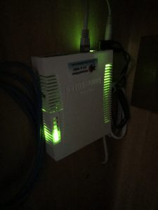
Router for Wifi Booster Installed!
Posted in Electronics and Radios, Sailing by Mark with comments disabled.
Navigation Project Part 2
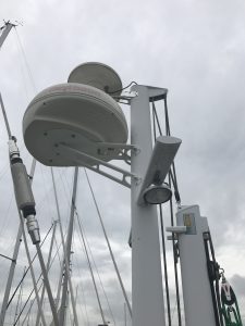
Radar Mast on Good Karma
Well, figuring out how marine electronics are supposed to work and coming up with a good installation layout is proving to be a challenge. Despite having an enormous amount of knowledge of electronics and computers, marine electronics are in their own special world. The things you’d think would be similar, such as a chart plotter and something like an iPad (both can be used as graphic navigation computers), are not at all.
By the way, this post will be quite boring to most so feel free to stop reading if you aren’t interested in this topic.
Also, wiring is a huge challenge. Ok, so you have a radar unit, which is the big round bowl-looking thing in the picture above, that works with the chart plotter. The chart plotter displays a chart (map) of the area and shows your boat location, like Google maps. Separately, the radar overlays on the map non-static items such as weather, boats, etc. Seeing where boats are is invaluable when navigating in fog or at night. For instance, when we sailed in the San Juan islands off Washington state, a fog bank came in rapidly while we were in a busy channel. Out of the gloom we heard a loud ship horn, ran to turn on the radar (an old clunky one) and could see where the ship was. We could then keep clear. So it is fairly important.
Anyway, the point is that the radar data has to get to the chart plotter which is in front of the wheel. To get the data to the chart plotter, you have to run a cable down the inside of the mast, under the cockpit deck and up to the chart plotter. Running these wires is quite the job. You would think a modern system would use wifi or bluetooth. You would think that all modern instruments would be connected this way, it would be far easier to install and maintain and maybe not quite as reliable, probably reliable enough.
Turns out the radar DOES have a wifi channel to the chart plotter BUT… They recommended wiring it up anyway and using the wifi as a “backup.” That actually makes no sense but whatever.
This all started because we wanted to install an AIS system so big ships can “see” us and we can “see” them. A new AIS required a new chart plotter which required a new radar. BUT, our current electronics are quite old and though they still work, they are very dated and it shows. A new system makes everything safer and given the amount of sailing we intend to do, we will need it.
By the way, click here to see a cool video of ship traffic around the world taken from AIS transponders. Lots of traffic out there!
Posted in Electronics and Radios, Sailing by Mark with comments disabled.
Radio setup
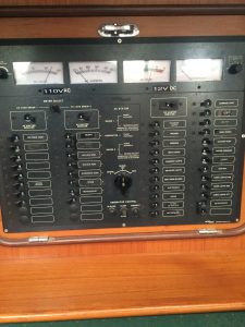
You Might Be Happy Not to Have to Deal With This Every Day
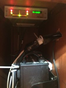
Pactor Modem (above, with lights) and Marine SSB Radio Below
One of the first systems I tackled on the Good Karma was the ssb radio. Nothing is easy and this proves the rule. The importance of this radio is that it is a long distance communication system, like over a thousand miles. This is necessary for ocean travel where your only communication link may be this radio. Here is my experience, skip this if you have no interest in radios:
This is a long-winded essay about how to patch together a circa 2002 model ICOM M710-RT marine band SSB radio, a Pactor modem, and a modern Macintosh MacBook Air to work as an email system. This is about hacking old technology and new, incompatible systems to make them work together, like something they’d do on Star Trek.
My recently acquired sailboat has a Marine Icom M710-RT SSB radio and a Pactor II Pro modem (with pactor III firmware upgrade). You can set this radio up to send and receive email over HF frequencies while out at sea far from land. The data rate is slow so only small data sizes are practical, like text email.
A system called “Sailmail” uses the marine bands to send and receive mail. Unfortunately, sailmail is a subscription service that costs a bit over $200 per year to use. Sailmail depends on a system called “winlink” to work. Winlink is a radio email service set up by amateur radio enthusiasts (hams).
Because amateur radio cannot charge for services, winlink is free IF you have one of the advanced amateur licenses AND an amateur radio. I have the license. All I needed was the radio set up on our boat.
Getting the radio set up was an issue. I have a Yaesu FT-993, a great amateur radio, but I would need to install it and supporting systems to get it to work. And on top of that I’d still need to keep my ICOM for marine band operation as the Yaesu would not operate on those frequencies. (Note: I probably will install my amateur radio in the future as it is a far more versatile radio on ham frequencies).
But I also knew that a trick radio manufacturers use to keep their costs down is to build one radio that they can enable for whatever market they want to sell into. So essentially the same generic radio can be built and then set to work on ham freqs or marine freqs or police freqs, for example. These radios can be enabled to work on all frequencies they are built for, the trick is to know the secret modification and do it yourself.
In the old days this was accomplished by cutting traces on a board or some simple hardware modification. Since the late 1990s, almost all radios can be changed by reprogramming the firmware.
So I knew both of these radios could be programmed to work on both amateur and marine freqs. And it seemed pretty straightforward to choose to reprogram the system I already had in place. Another technical reason to try to reprogram my ICOM – it is legal to use the marine radio to transmit on amateur freqs but NOT legal to use the amateur to transmit on marine band freqs. Why? Because the FCC wants only approved radios transmitting on controlled bands like marine, police, fire, etc. The amateur band allows a lot more leeway, you can pretty much use any radio as long as you don’t exceed the limits of the band, like keep the power under the legal limit. So the marine radio can transmit on ham bands, you must have an amateur license of course.
So I set out to get my marine band radio modified and working on ham bands.
The ICOM M710-RT is a great, though somewhat dated radio. I also have a Pactor II pro modem, an expensive system that would be quite expensive new, I believe greater than $1000 for an out-of-the box modern one. The modem can be controlled by a computer via a serial cable.
The system connection is as follows: Computer ——-Pactor Modem———Icom Radio
The connection between the modem and the radio is already in place and there is no need to mess with it. The computer-to-modem connection is an old 9-pin serial port, not built into Macs. Fortunately, there is also a Keyspan USB-to-serial adapter in place so at least I can use a USB port that IS on my Mac.
I consulted several web forums about getting this stuff to work together and what has been successful or not, and after experimenting a lot I finally got things working after about two weeks. I am an expert in software, devices and radios and this still took me about two weeks, it was NOT easy. Here’s why:
Winlink is a Windows program, there is no Mac version and I’m not sure if Winlink has been updated at all since 2008 or so. I have a Mac. You can run Windows programs on a Mac using various tools, some are better than others. A program called “Crossover” was recommended by many and so I bought that. Not too expensive if you don’t need tech support. Considering that we live in a world of shareware, it’s actually quite expensive however.
Then I needed to get the Keyspan USB driver for Mac. Pretty easy, it’s online. Unfortunately it took a while to realize there was no native driver available, my Mac did not warn me when I plugged the Keyspan in.
Getting Crossover to work was not difficult. I set it up to run a Windows 7 environment. Crossover does not come with a lot of OS support and you have to “install” utilities such as an unzip utility. This is required so that you can unzip the Winlink software and install it in your emulated Windows environment. There is also some funkiness setting up the serial COM port emulation to USB on a Mac, but not really difficult and there are good write-ups out there on the web about how to do this.
Winlink is not extremely user friendly but it’s not hard to figure out and there are youtube tutorials out there.
The big test was to determine if Winlink can talk to the Pactor modem. After a few tweaks, got it working and the first message to pop up was “You need Firmware version XXX to run Winlink on this modem.” I needed to update the Pactor modem firmware. That’s pretty easy to do, the company SCS has all the firmware and tools necessary to update the modem.
So, modem firmware updated. Next I tried to send some radio email via a Winlink station. No can do, my Icom would not allow those frequencies. Winlink won’t let you use the Marine frequencies either, you need Sailmail to do that.
Now it gets fun, trying to update my Icom firmware.
First I email Icom and ask for the tools. They said they can reprogram the radio but I have to get it to an Icom service center. That is absolutely ridiculous, I’d have to extract my radio and ship it to another state and wait for them to get around to it, and probably have to pay a few hundred dollars for the privilege.
I did some more digging around and found out that the Icom can only be programmed via a special DOS tool using a special cable. DOS. Didn’t that go away in the 80s? Wow. But not unheard of, it’s a legacy product supported by a legacy tool, not uncommon in the firmware industry.
What was more disturbing were claims that you needed to have a computer running DOS natively, not on top of Windows, and the machine had to have one of the old-style serial ports. Turns out that isn’t true if you get a good DOS emulator. That was better news. The recommended emulator was “Dosbox,” it’s free though they ask for a donation.
There is a Mac version of Dosbox that works well. Next, get the Icom software tool and a cable. Search around through the various forums and google, and you find references to an app called EX1726.EXE. The tool has been pirated and is out there if you look. The cable is an OPC-478.
Next get a USB-to-Serial programming cable for the Icom. Ebay has several so I ordered one, shipped to the marina in a couple of days. Plug it in to my computer and Icom radio (and another USB driver from the web). Set up a Dosbox serial port and run EX1726.EXE in my emulator.
Seemed to be working, but in reality I had no real feedback that it was working at all. This was a simple firmware read-modify-write program. I’ve written these apps and even had a patent on a certain aspect of reprogramming a device way back when. Anyway I knew what was “going on behind the curtain” so I tried the function that reads the memory and got a “clone error.” It wasn’t working.
I dug around a bit more and found a Yahoo group dedicated to the M710. I joined and bingo. All kinds of tech information on this radio and pirated software. Turns out the cable I got was for the M710 but doesn’t work on the M710-RT. The cable type for the RT version is OPC-552 Also, the app needed was called EX2144.EXE made specifically for the RT version. Ok. Well, I’m confident I could have modified the cable I had to work but I didn’t have the parts available. Found another cable supplier on Ebay and ordered another cable.
Cable came in, fired up the radio and YES, I could program the radio. I enabled all the ham HF bands and went back to Winlink. This morning I was able to send and receive email over my SSB radio on ham frequencies. Success, but not recommended for the faint of heart.
Posted in Electronics and Radios, Hacking!, Sailing by Mark with 2 comments.
Bioelectric Signal Project
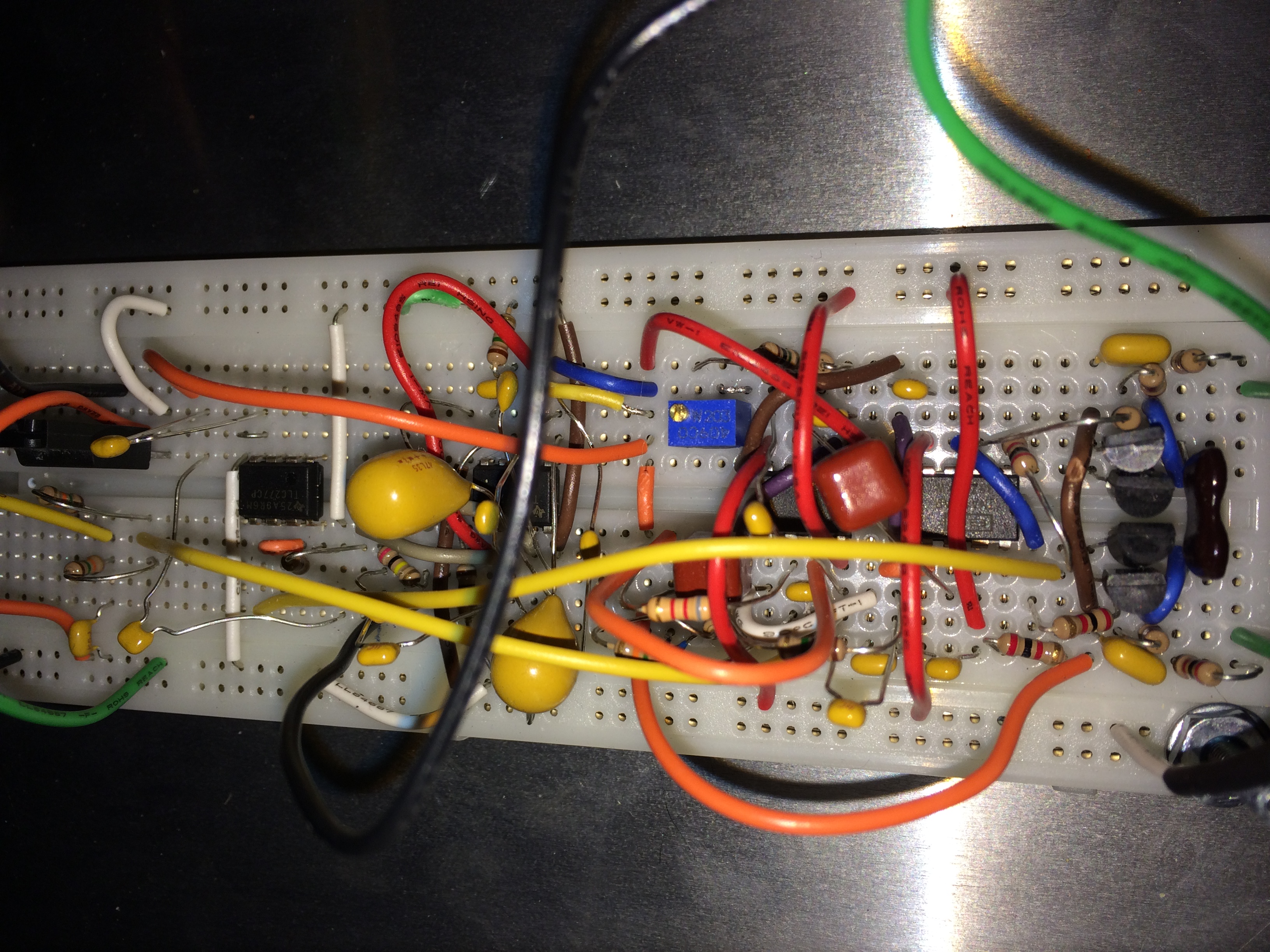
Amplifier/Filter board
Last year I heard a radio interview on National Public Radio about a device that people were building to “enhance cognitive ability,” called a transcranial direct current stimulation, or TDCS device. The claim was that this device could enhance cognitive ability, such as increase memory retention, concentration levels, and problem solving ability, and even enhance your mood. It accomplished this by applying a low-level DC current across your head for up to 20 minutes at a time.
It turns out that this is not the flaky idea it appears to be. It has been studied for decades by psychologists, and even the US military performed a study in the 1960s with interesting results. So I decided to test this out myself. It turns out that you can build one of these devices with a few parts commonly found at electronics stores. So I built one.
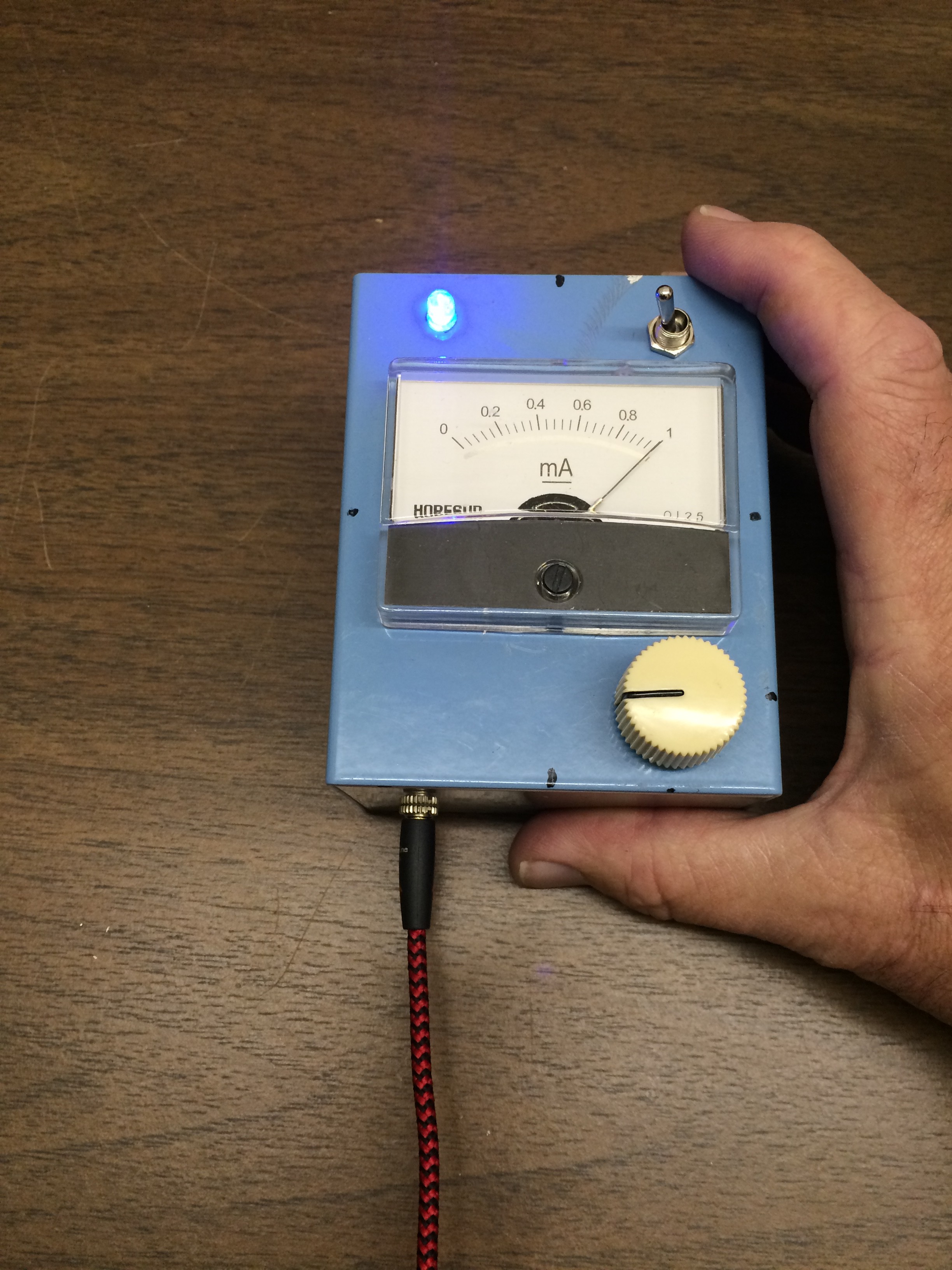
My tDCS device: It works!
I tested it a few times and did notice something, though it is difficult to describe. It could have been a placebo effect, but it is easy to imagine that this current is causing some sort of reaction in the brain given one of the brain’s essential characteristics is easily measureable electrical activity.
So I thought as my next experiment, it would be interesting to measure these brain signals for myself. This is commonly done using an electroencephalography machine, or EEG. Basically, this is an instrument that measures the minute electrical signals detectable from the surface of the skull. EEG machines have been around for nearly a century, used almost exclusively for medical or research purposes. That usually means they are expensive. So the first thing a do-it-yourselfer (DIYer) does is check the open source community.
The open source movement always eliminates the cost barrier, so I searched for an open source EEG. Voila, up pops OpenEEG.org. They had published the design of a DIY EEG machine, but it was somewhat obsolete having been originally designed almost a decade ago. However, it did contain good information, especially about how to build the “front-end,” the electronics that detect and amplify the brainwave signal.
The OpenEEG design had one big disadvantage. It required the subject to be physically attached to a personal computer, something that limits its use to wherever you can set down and plug in a computer. You couldn’t, for example, measure the brainwaves of someone climbing a cliff face. That was the limit of DIY technology a decade ago.
Things have changed.
Today we can build a tiny EEG machine that could be worn in a headband, eyeglasses or some small, unobtrusive wearable item. And it need not be physically connected to a computer at all. A smartphone or tablet application could display data collected by the EEG device, either in real-time or downloaded after the fact. And it would not be that difficult to build given the low-cost prototyping tools and devices available today.
So I decided to build a prototype wearable EEG device, pulling together information from various open source sites including OpenEEG. After several months I had a working prototype that could display brain waves. And interestingly, it can detect and display other bioelectric signals. I can measure the waves produced by my heartbeat. I can see the signals that control muscles. As a matter of fact, when hooked up as an EEG, the device displays jaw muscle movement, and even the movement of my eyes.
What I built is a prototype of what could be a small, low-cost, wearable EEG. Imagine the possibilities if it became a popular product where the bio signals of tens of thousands, or even millions, of people could be analyzed. The signals produced by muscle activity are relatively well understood when compared to EEG signals. EEGs are used as medical devices but in extremely limited ways such as determining where seizure activity originates in the brain.
Though we can measure and categorize EEG signals, the fact is that medical research has provided scant information as to what those signals mean. Now imagine that medical research had access to tens of thousands of EEG signals of people doing a wide variety of activity.
What could be mined from such a database? The possibilities are amazing. Could it help individuals improve memory, thinking, or concentration? Enhance emotional well-being? Help with psychological abnormalities or mental illness? Improve early detection of brain abnormalities or tumors? Who knows what could be discovered.
So back to the prototype, the idea is this: Build a prototype wearable EEG device that can communicate wirelessly with a smartphone or tablet. An application on the smartphone or tablet would display the data in various forms, such as a real-time wave, or a processed signal that is easily interpreted by a user. This data could then be collected by the application, associated with an activity and other bio data and uploaded to the cloud. Anonymized data could be entered into a greater database.
What the prototype needs is a front-end circuit to get the signal. EEG signals are tiny, so the signal needs to be amplified and filtered to be of use. The signal then must be digitized and possibly stored. It then must be radio transmitted to a computer for further processing and display. If this computer is a smartphone or tablet computer, an application can be written that not only displays the data but also updates a cloud database.
This writeup will not go into every detail of the EEG machine I built, but I will discuss each of the major components for my prototype. They are:
An amplifier/filter front-end circuit
An Arduino Uno
A Bluetooth Low Energy (BLE) board
An Android tablet
Not mentioned in the list are the tools necessary to build and test the device. Also, it should be noted that this is a challenging project, especially if you build the amplifer/filter board from discrete components as I did.
Amplifier/Filter Front End: The bioelectric signals we want to detect are in the microvolt range, that is, one thousandth of a volt. Pretty weak. We need to amplify this to the single volt range to be usable. Also, these waves are very low frequency, basically 60 hertz and less. We don’t care about any signals greater than 60Hz.
One thing we have to consider is that all electronic circuits “pick up” electrical noise from the surrounding environment. This noise may be very small, but so is the signal we are trying to see. Therefore, we must take measures to shield our circuit to minimize spurious noise. Because shielding is not perfect, we will also need other measures to get ride of noise, namely an electronic filter. A big source of noise is power lines, all of which run at 60 hertz in the U.S. But remember, we only care about zero to 60 hertz, so we can design a simple filter that suppresses all signals greater than, and including, 60 hertz.
Our circuit is a three-stage amplifier that can amplify up to 10,000 times and filters signals greater than 59 hertz. It also biases the signal positive for digital conversion. I adapted this circuit from OpenEEG.org (which adapted it from a scientific research paper), along with a screen cap of an unfinished board layout made with Eagle CAD (computer aided design) software.
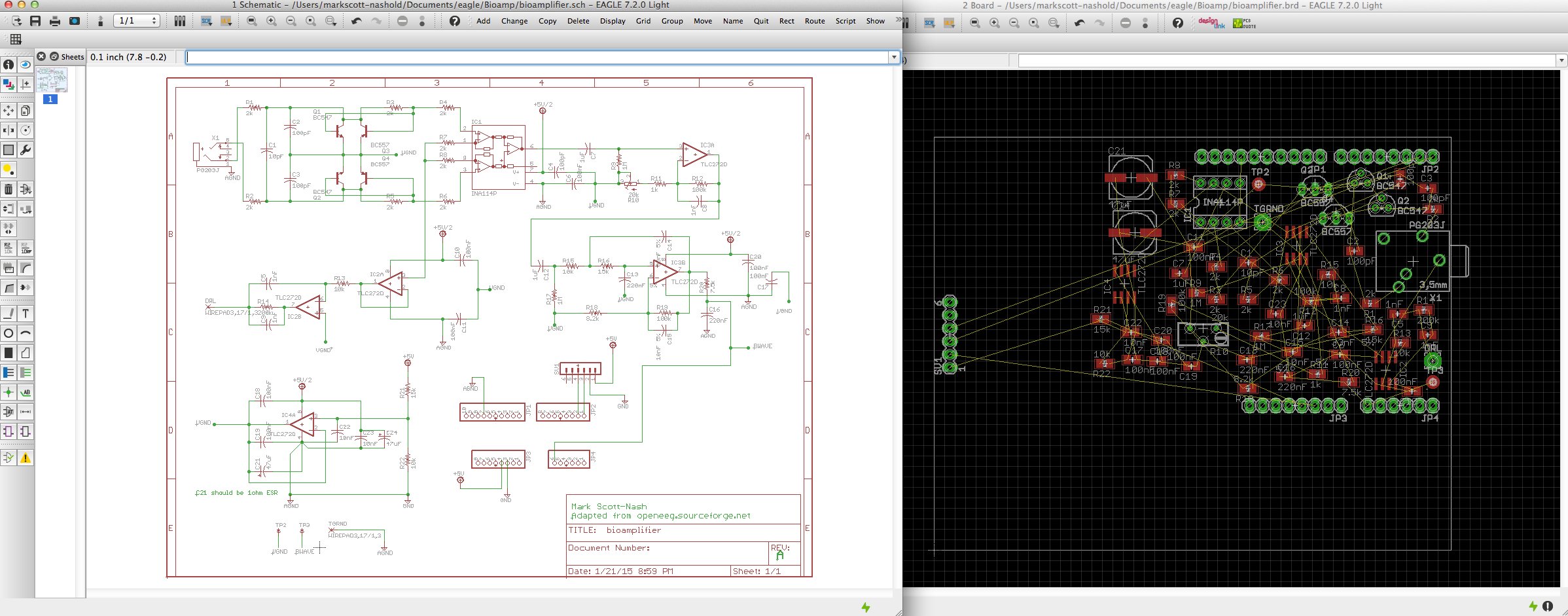
Schematic and board layout (unfinished) using Eagle
I built this circuit from discrete components on a prototype board, shown at the top of this blog post. This is not recommended unless you have advanced circuit debugging skills and tools, or know someone who does. The reason is because there are more than 50 individual components with more than 100 connections between them. It is essentially impossible to build this circuit by hand without making a mistake, and likely several, that will render it inoperable and turn this into an exercise in extreme frustration.
To shield this circuit, I put it in a metal project box. The input to this box is a fully shielded, two-channel audio cable that can be plugged into the probes. The output of the box is an analog signal that is fed into an Arduino, see below.
Arduino Uno Board: This board was chosen to provide and quick and dirty prototyping platform to digitize the analog signal and parse it for transmission, pictured below.
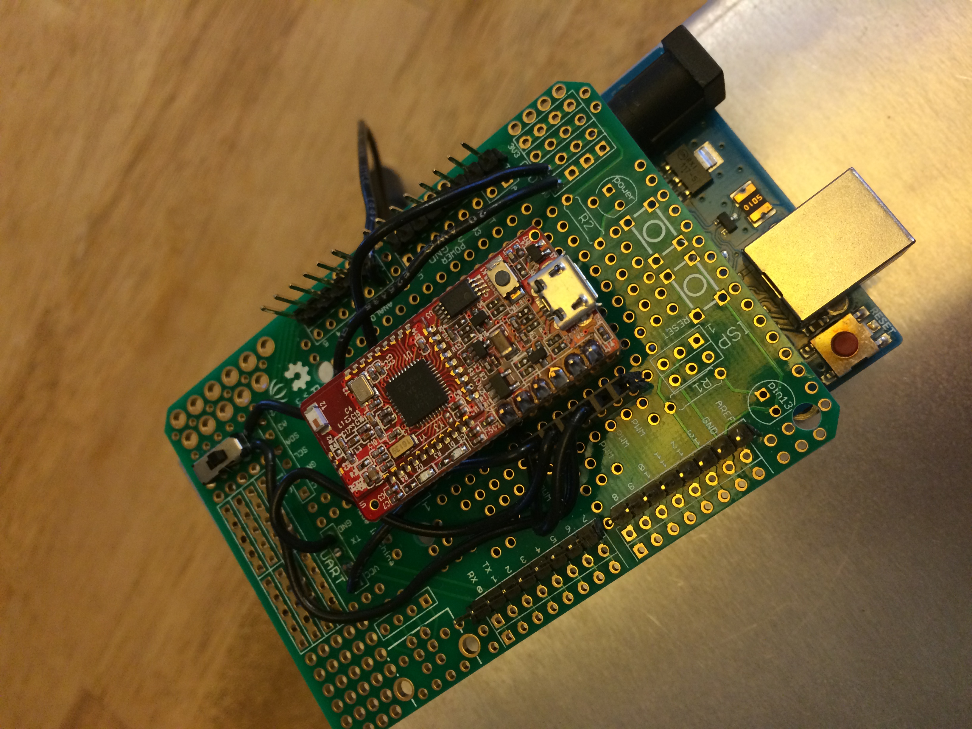
Arduino Uno with Bluetooth daughterboard (red board on top).
Note that the board is mounted outside the front-end shield. This is intentional. First, the Arduino is not nearly as sensitive to noise and does not need shielding. Second, digital electronics actually generates lots of noise and would interfere with the front-end board, so it needs to be outside the shield. Third, it is convenient.
Basically, we feed the analog wave signal into one of the Arduino’s analog-to-digital converters. An A/D converter, as it is called, takes the amplitude of a signal and converts it to a number. For instance, 0 volts will translate to the number 0, and 5 volts will translate to 255. A level of 2 volts would translate to 102. This translation happens in a fraction of a second, a “sample” is saved and another translation is done. This time interval is called a “sample rate.” If the sample rate is fast enough, we can get a good representation of a rapidly changing input signal as a series of numbers.
We then package these numbers and push them out to our radio transmitter, see below.
The Bluetooth Low Energy Board: This is a Bluetooth transceiver prototype board that conveniently plugs into an Ardunio prototype shield board. This is a little radio that allows us to connect to and transmit data to another device like a tablet computer. This board contains its own processor and firmware and automatically handles the Bluetooth protocol on the device side. We send data packets from the Arduino to the Bluetooth board, which then packages and transmits the data wirelessly to our tablet, described below.
Android Tablet Computer: I used a Samsung Galaxy S5 mini-tablet computer because I had one available. I developed a prototype Arduino application that connects to my front-end device using the Bluetooth protocol available in the device. I can display the bioelectric wave, the power of frequency bands and a chart showing trends in the power, more about that below in the Android App section.
Android App Notes: As with the hardware, this is a prototype application and not a full working version as you might expect with a commercial product.
What it does: Connects to and captures data packets from the front-end via Bluetooth, and displays this data in both wave and power form.
What it doesn’t do: There is no support for recording or uploading to a cloud server in this version.
The power display is used mainly for when EEG signals are being detected as these signals have been classified into various frequency bands Delta, Theta, Alpha, Beta and Gamma. The power display can be interpreted as how much of each of these bands is measured so the change in power is visible.
The power display is exactly like a sound equalizer display except that it is tuned to bioelectric signal frequencies rather than audio frequencies. This is accomplished by processing the wave data through an algorithm called a Fast Fourier Transform, or FFT.
Results: One of the more difficult aspects of this project was coming up with a low-cost design for the electrodes you attach to the skin to pick up the biosignals. I ended up making simple electrodes made of small steel washers. These worked quite well if you also use Ten20 conductive gel (quite cheap) and hold the electrodes in place on the skin with athletic tape.
I could easily detect heart and muscle activity. Detecting brainwaves was tricky, but I concluded this was due to the quality of the electrodes and not the electronics per se.
There is a demo Youtube video of the hardware being turned on but not actually connected to electrodes here. What you are seeing is a sequence of starting up the Android app, turning on the front-end electronics and then a display of various forms of the data being received. This demo does not have the electrodes connected so what you are seeing on the display is noise and the electronics settling. The top display is a representation of the wave (in this case noise) being sent from the Arduino via Bluetooth. The next display down shows the power spectrum from 0 to 60 hz. The third display down from the top is specific for an EEG setup: These are the power levels of the types of EEG signals Delta, Theta, Alpha, Beta and Gamma waves. The final display is a long-term trend graph of the power of the EEG signals.
The most impressive working demo is detecting a heartbeat as shown here. Muscle contractions associated with moving my fingers are demonstrated here, and an actual EEG signal (measuring my brainwaves) is shown here. For each of these demos, I simply changed the location of the electrodes on my skin.
Though the front-end box is quite large for something intended to be wearable, keep in mind this is a prototype to prove the concept. An actual product would be much smaller, just a few square inches in size.
There is great potential in turning this into a product, but my main interest was to put these various technologies together and having fun building both hardware and software to make a new device.
Posted in Electronics and Radios by Mark with comments disabled.
Bugsville
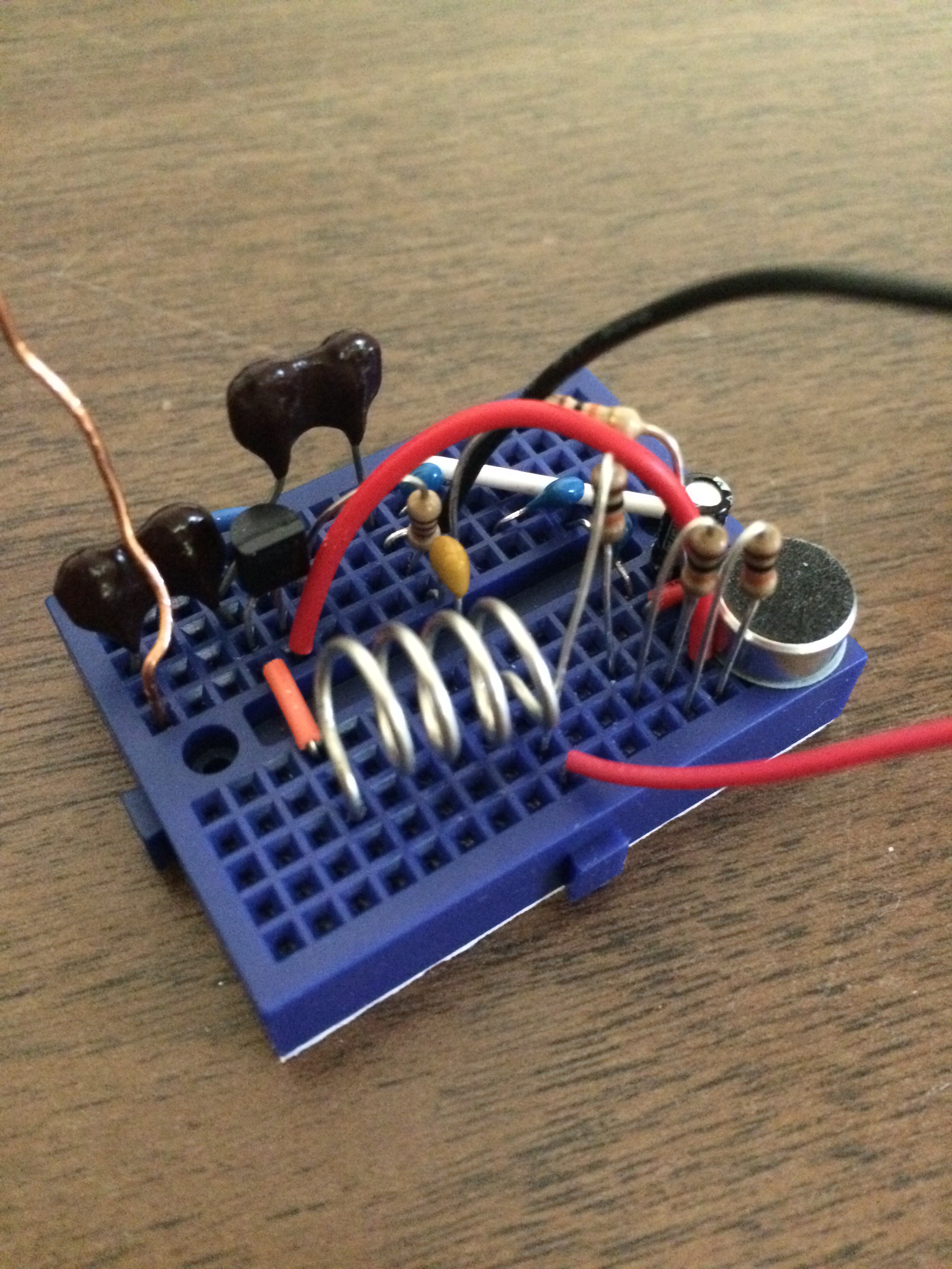
FM Transmitter
Ok, a few postings as I have been gone from this blog for a year. Reboot.
Above is a pic of a simple FM transmitter that picks up ambient sound in a room, such as talking, and transmits it at a frequency that can be picked up by any FM radio. Less than 20 simple parts, it works amazingly well for such a simple circuit. It contains one transistor and a microphone I salvaged from an old FRS radio. The silver wire coil is handmade, just a piece of wire coiled around a pen. This is not my invention nor is it anything new, but it is quite an effective short-range transmitter “bug” that I’m sure has been replicated thousands of times by amateur “spies.”
Posted in Electronics and Radios by Mark with comments disabled.