How To Build A Laser
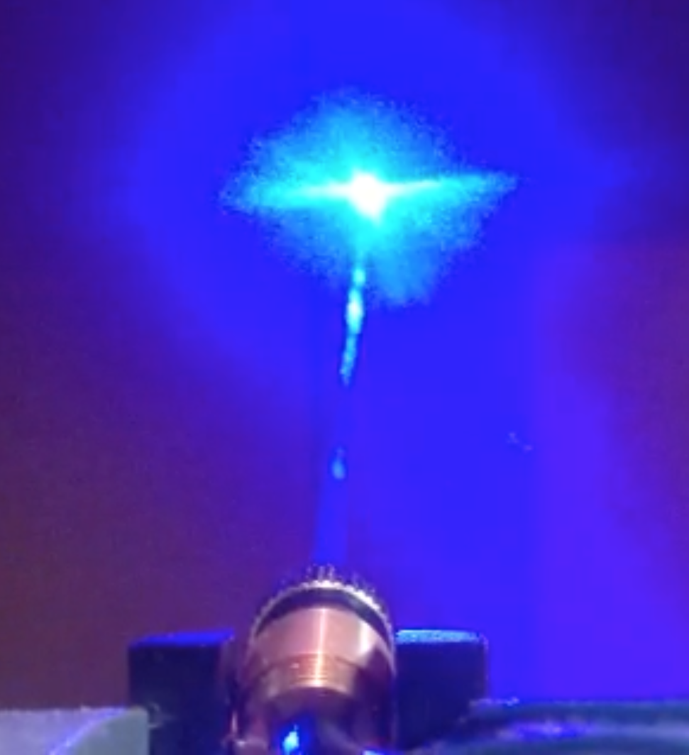
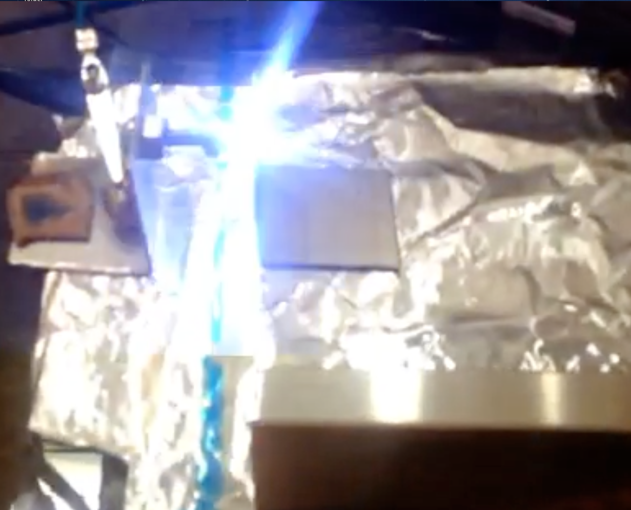 6500 Volt Spark Gap Flashes Immediately Prior To Laser Firing
Ok, here is how to build a low cost laser using easy to obtain parts.
This is what you need and where to get it:
- High voltage DC power supply that you can make from a neon sign transformer as described here.
- Three sheets of aluminum foil – grocery store.
- Thin plastic vapor barrier sheet – hardware or flooring store.
- Aluminum right angle bar – hardware store.
- Copper wire – hardware or electronics store.
- A one watt resistor of any value between 10K and 1 meg ohm – electronic parts store.
- 1 inch long bolt – hardware store.
- Nut for above bolt – hardware store.
- Round capnut for above bolt – hardware store.
- Highlighter pen – department store.
- One sheet white paper – duh.
First, you need to cut the aluminum angle bar into several pieces using a hacksaw. The first two pieces should be about a foot long, the next two about an inch long. File down all sharp edges.
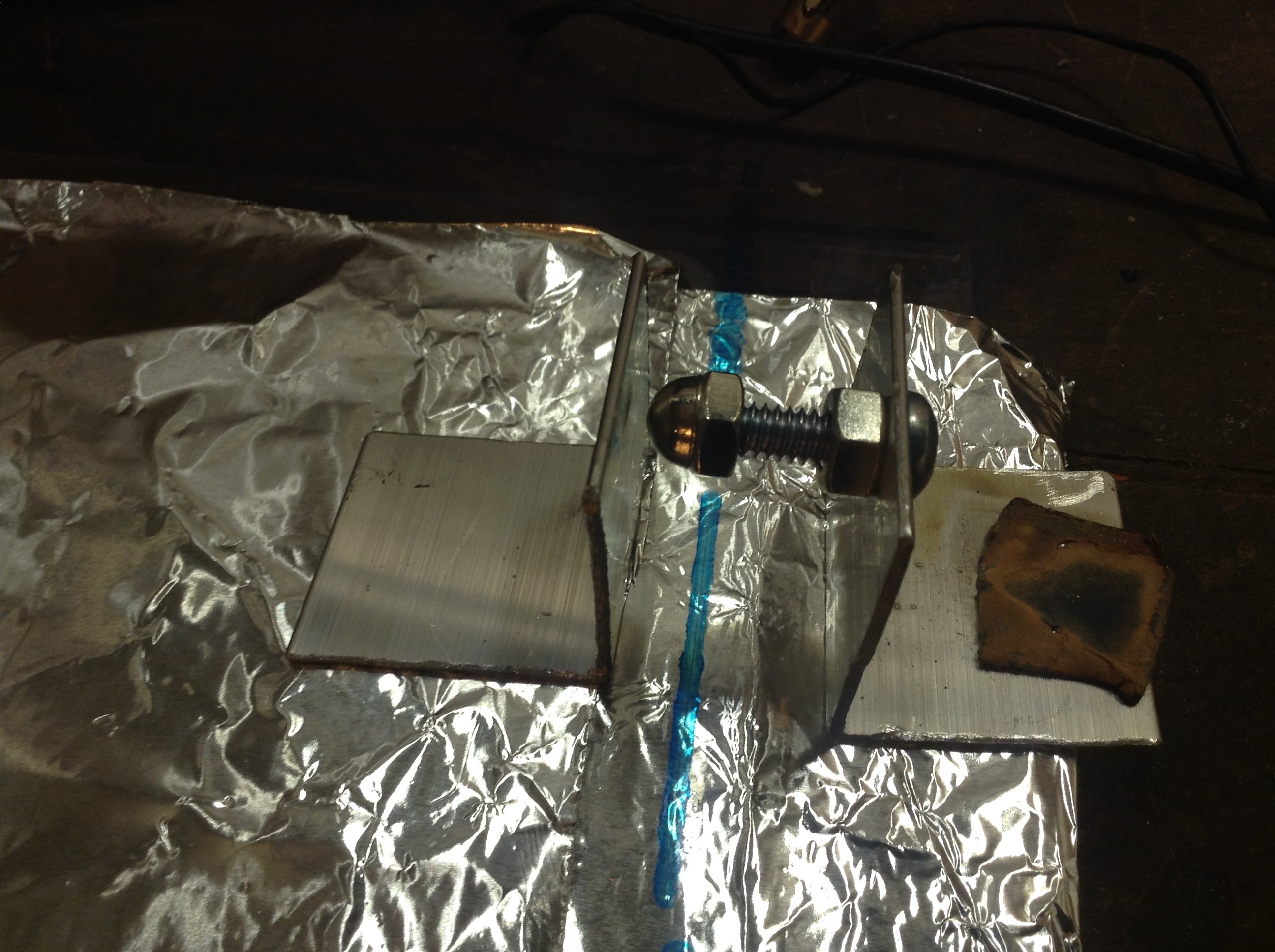
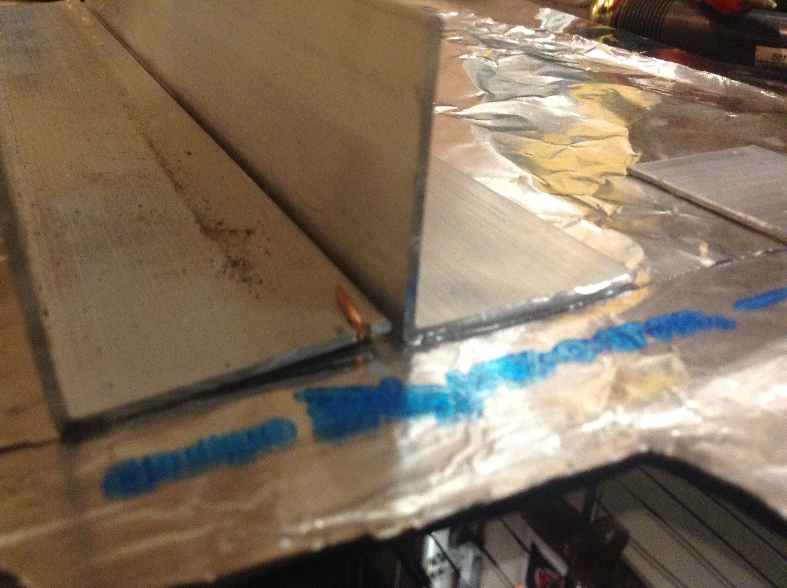
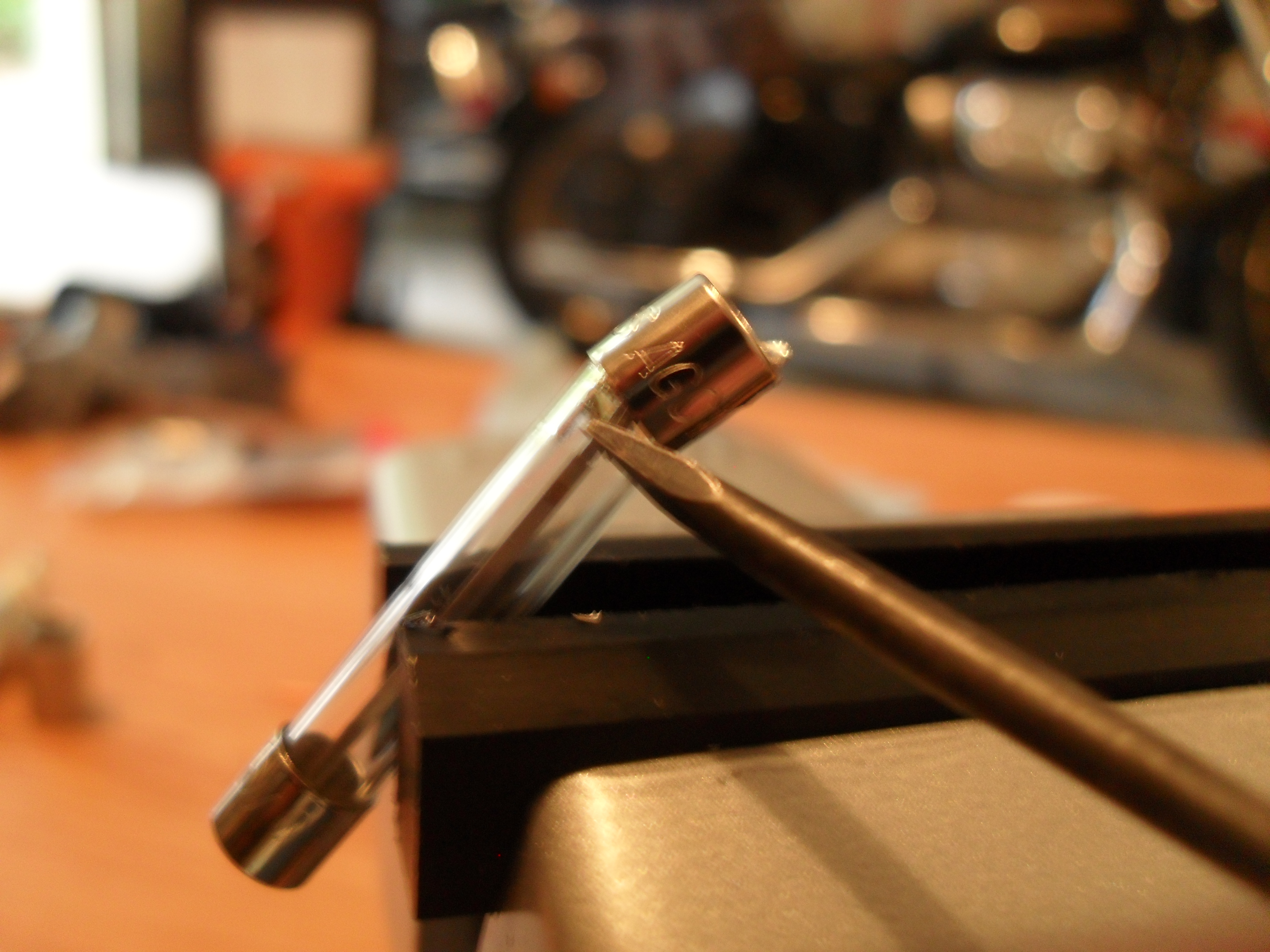
Drill a hole in one of the small pieces to put the bolt through. Construct the piece so that it looks like the righthand assembly in the above pic. This will be your spark gap.
With one of the long aluminum angle bars, cut two notches in each end. Stretch the copper wire between the two notches and fold it across them.
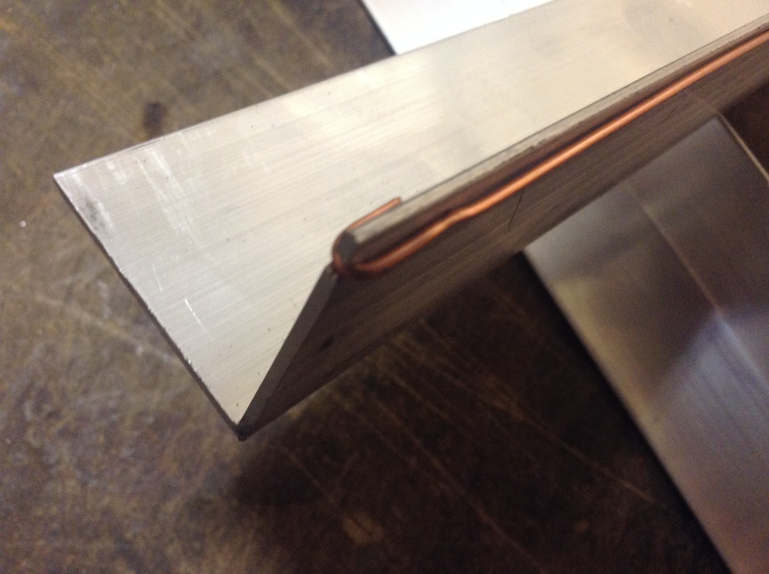
The wire should be very straight as shown above. The object is to make physical contact over the entire length of the aluminum bar.
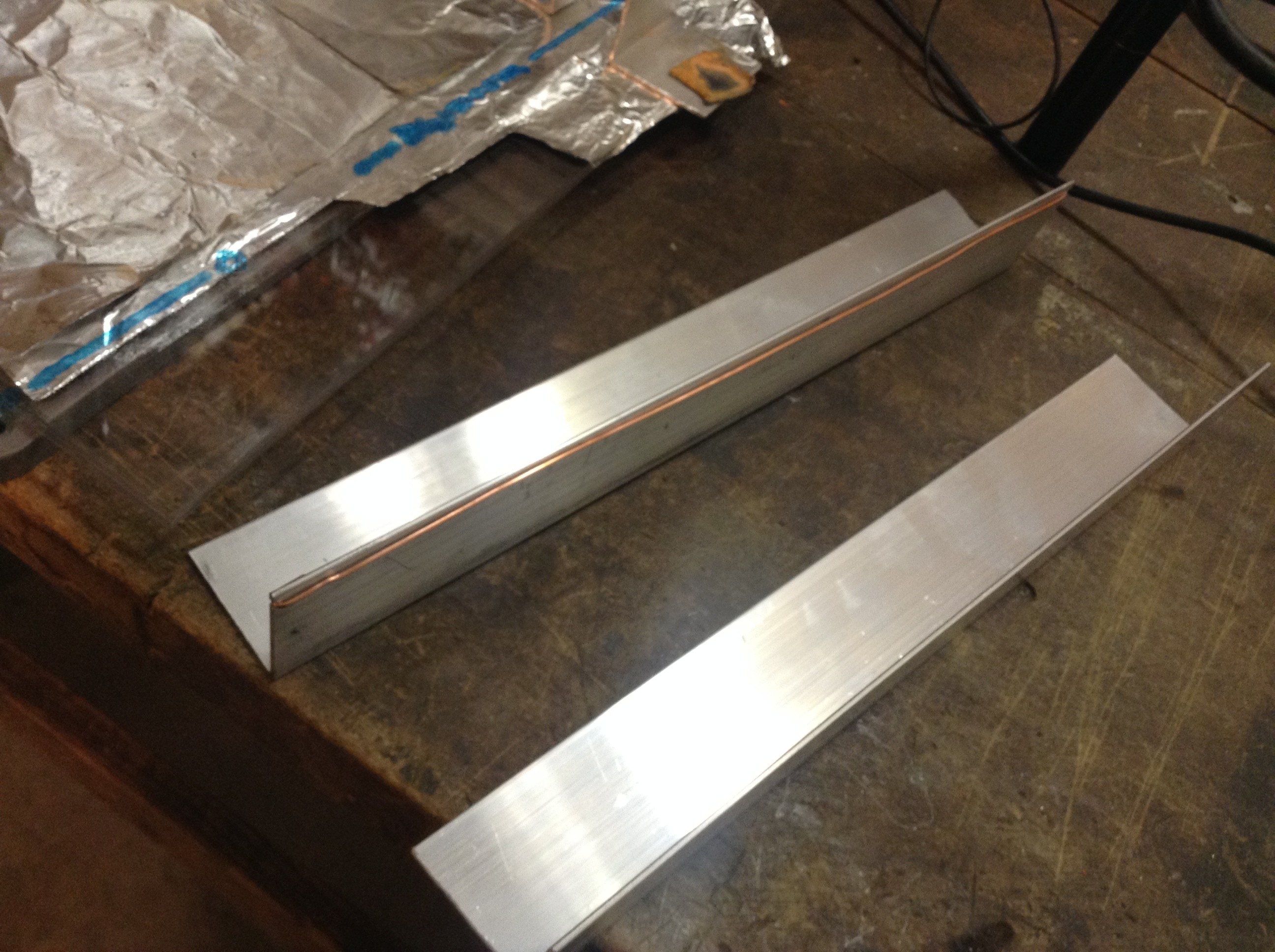
When you are done you the two bars should look as above, one with the copper wire as shown. These two bars will function as the laser electrodes with the laser light being produced between them. Next, you need to construct the laser discharge capacitors. It’s pretty easy to do.
Cut out a big sheet of aluminum foil with a tab on one side as shown below. Pretty much any size will do, a good place to start is one square foot.
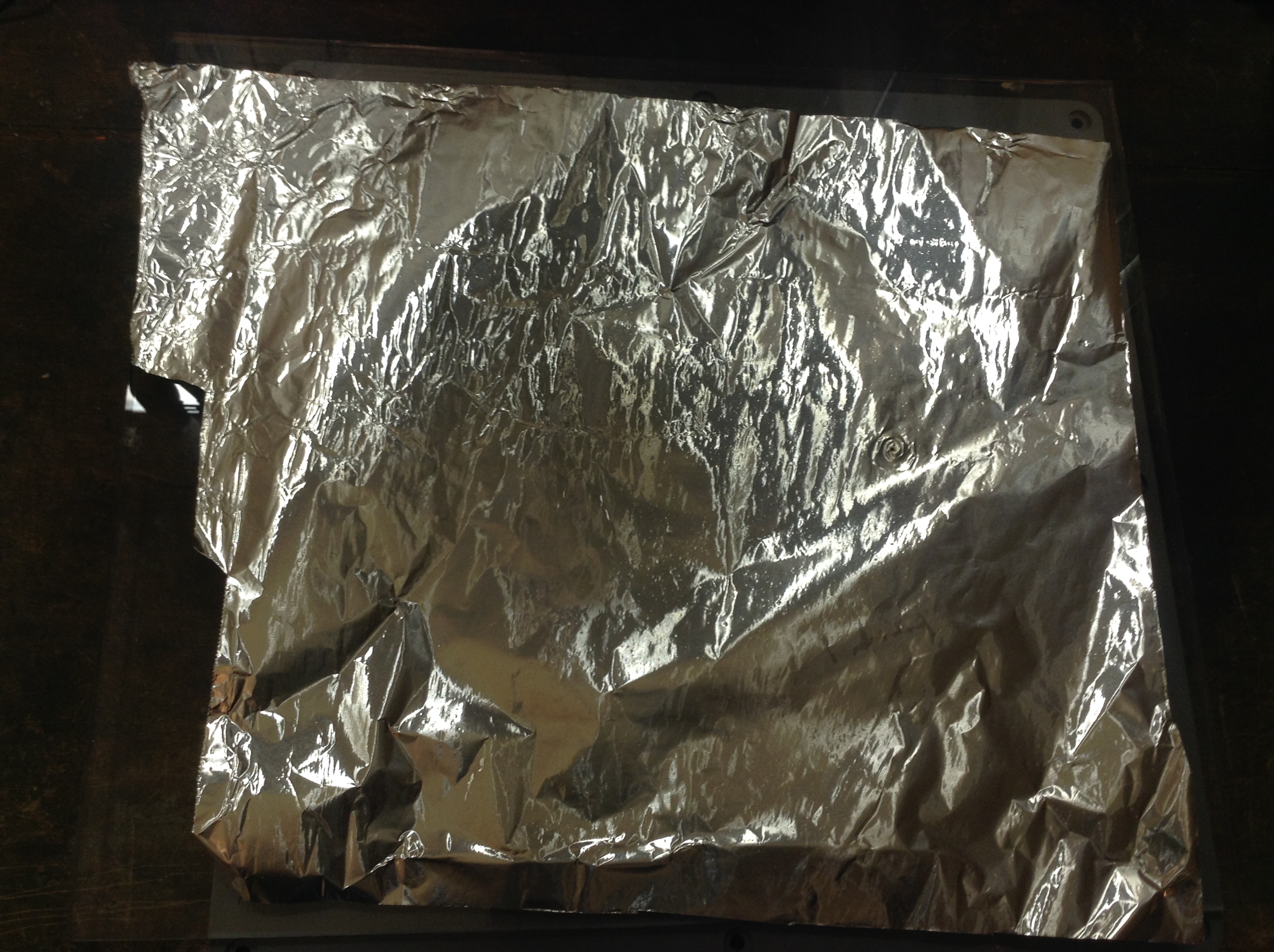
Next, cut a square of the thin plastic vapor barrier sheet. This sheet will lay on top of the first square aluminum foil sheet you cut. It should be the thinnest you can buy, probably around 4 mils thick. The plastic sheet should be cut so that it is about a quarter inch larger than the aluminum foil square below it on all sides except for the tab that sticks out to the left.
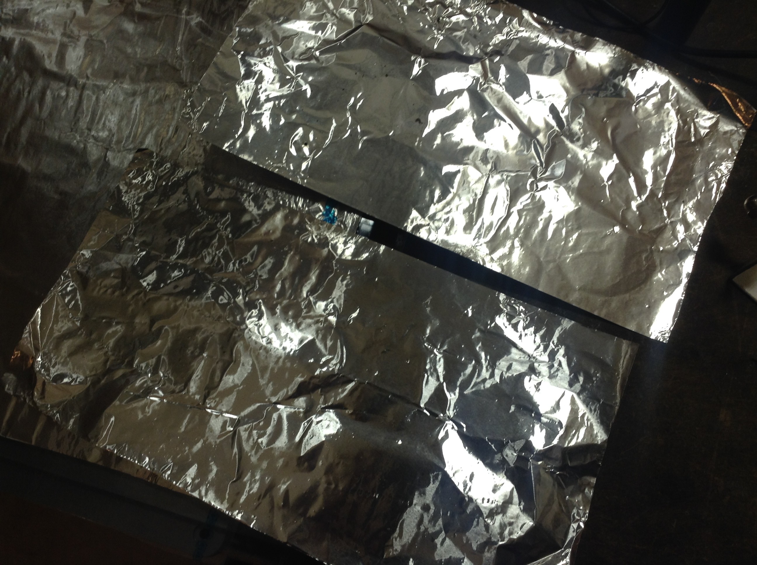
Next you cut two more aluminum foil sheets of equal size, a little less than half the width of the original sheet of foil as shown above. They will lay on top of the plastic sheet.
Align the two foil sheets so that they are 1/8″ apart lengthwise. The spark gap is shown in the upper righthand corner. One element of the spark gap is contacting one of the top aluminum sheets, the other end is contacting the bottom sheet where the tab protrudes from under the plastic sheet.
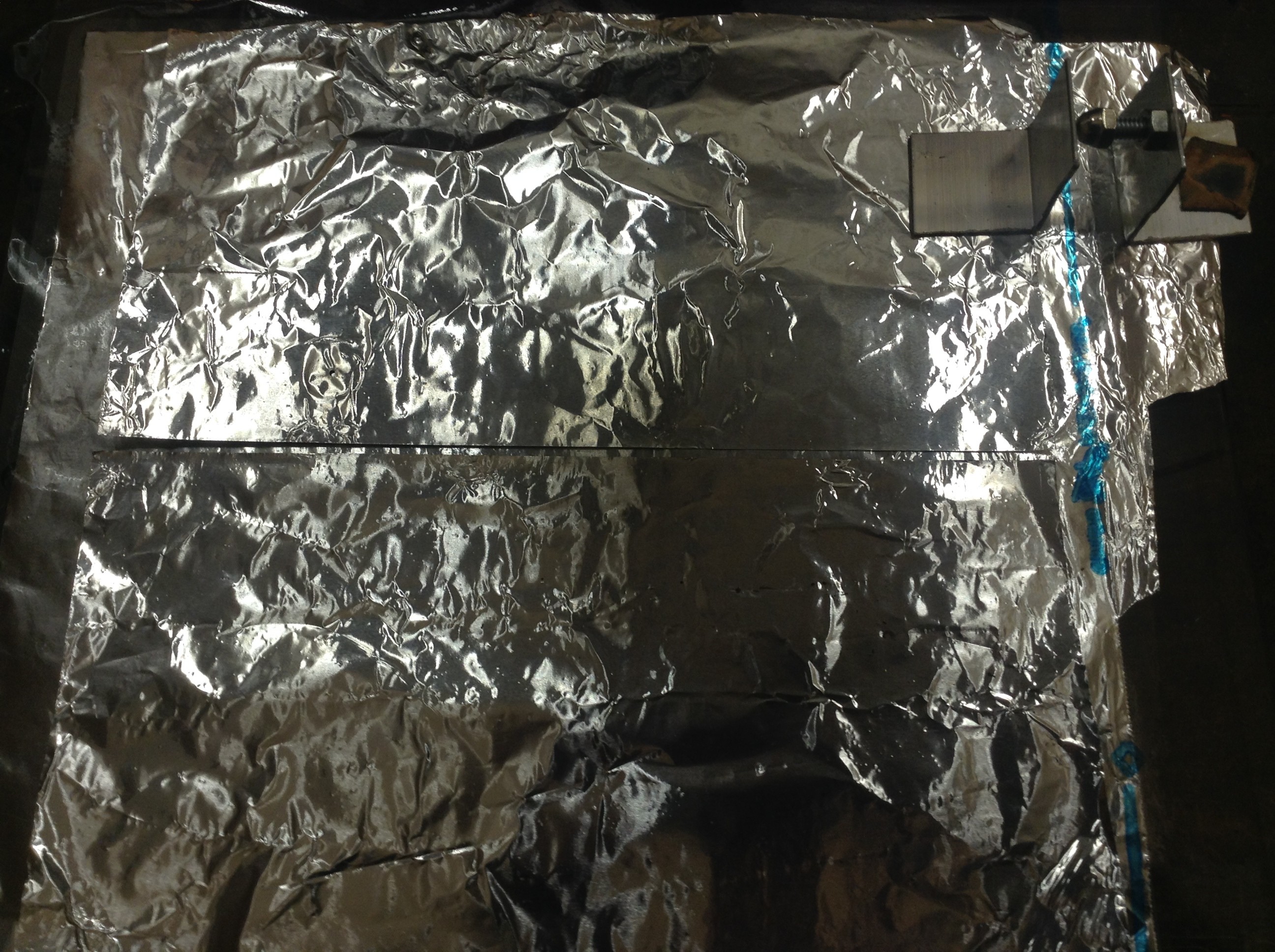
Next, you must place the two aluminum bars along the edges of the top foil sheets as shown above. Note that the copper wire must be in contact with one of the foil sheets and the other bar is simply sitting on the edge of a sheet. There should be a gap of one millimeter. This is easy to gauge, it is about the thickness of the wire on your one watt resistor. Make sure the gap between the bars is as consistent along the length.
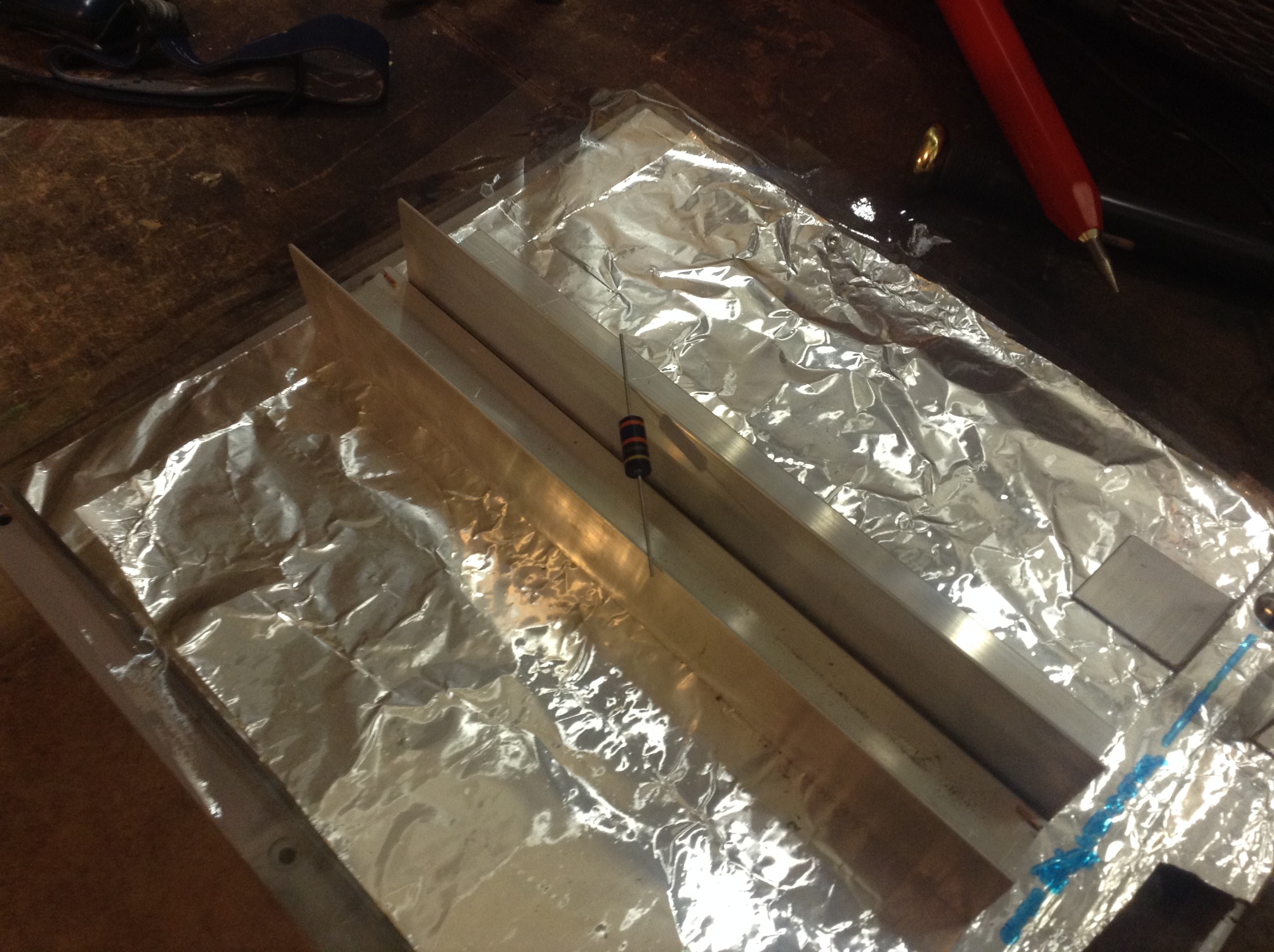
The spark gap is made of your two small angle pieces. Place on piece on the bottom foil tab protruding from under the plastic sheet. Place the other on top of the top aluminum sheet. The spark gap is between the cap bolt and the flat face of the other small piece of angle beam. Lastly, place the resistor across the top of the laser. It just needs to touch each of the electrodes as shown above. To add reliability, weigh the beams down on the aluminum plates using small rocks.
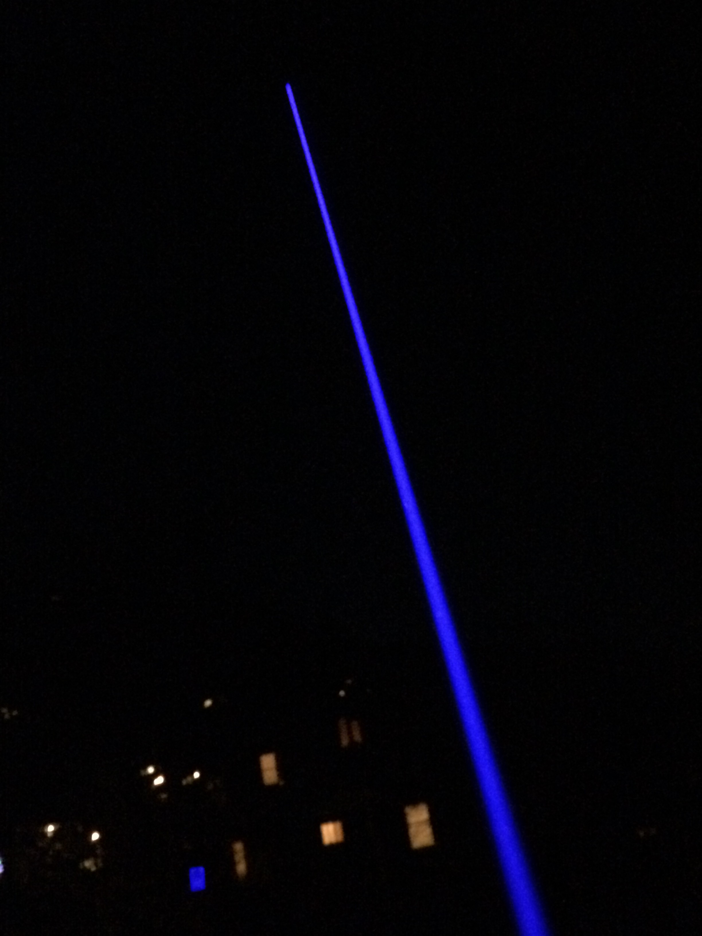
The power supply should be applied to each end of the spark gap pieces. The gap should be approximately 1/8″ so that the capacitors will charge to around 6,000 volts before firing. You can see the beam that is formed in the small lengthwise area between the electrodes and shines in the lengthwise direction from the electrodes. The beam is a momentary pulse that shines immediately following a spark gap firing.


The beam consists of invisible ultraviolet light. To see it you need to place a material that fluoresces in ultraviolet. This is easy to do. Both highlighter ink and white paper will fluoresce in ultraviolet light. Paint a square on your white paper using your highlighter pen or simply place the white paper in the beam line. The above photos show the ultraviolet beam fluorescing green highlighter ink on the left and white paper on the right.
This is a Transversely Excited Atmospheric laser, or a T.E.A. laser. All lasers need a material, or medium, that “lases.” This means that a material, which can be a solid, liquid or gas, is “excited” by some energy such as a high voltage, and has the right properties to allow stimulated emission to produce laser light. It turns out that the lasing material for this laser is nitrogen. Remember that 78% of air is made of nitrogen. It need not be pure nor at some exotic high or low pressure for this to work. We know that the lasing material is nitrogen because the ultraviolet frequency emitted is associated with characteristics of the nitrogen atom.
Here is a video of the laser in operation. Turn your speakers down, the spark flash is loud…
Posted in Journal, Nuclear Fusion Reactor by Mark with comments disabled.
Garage Laser Experiments
Blue Laser in Night Sky
Ok, here are some of my recent laser experiments. Kids, don’t try this at home…
First I went out to the web to see what was the most powerful laser I could purchase for a reasonable price. What I found was someone selling the generator from a laser welder. It was pretty cheap so I bought it. I then bought a used power supply that could deliver 30 amps at 5 volts really cheap at an electronics surplus store. The power supply would deliver up to 60 amps so I built a resistor array that would limit the current to 25 amps and added a push button to turn the power on. The resulting setup is shown in the picture below.
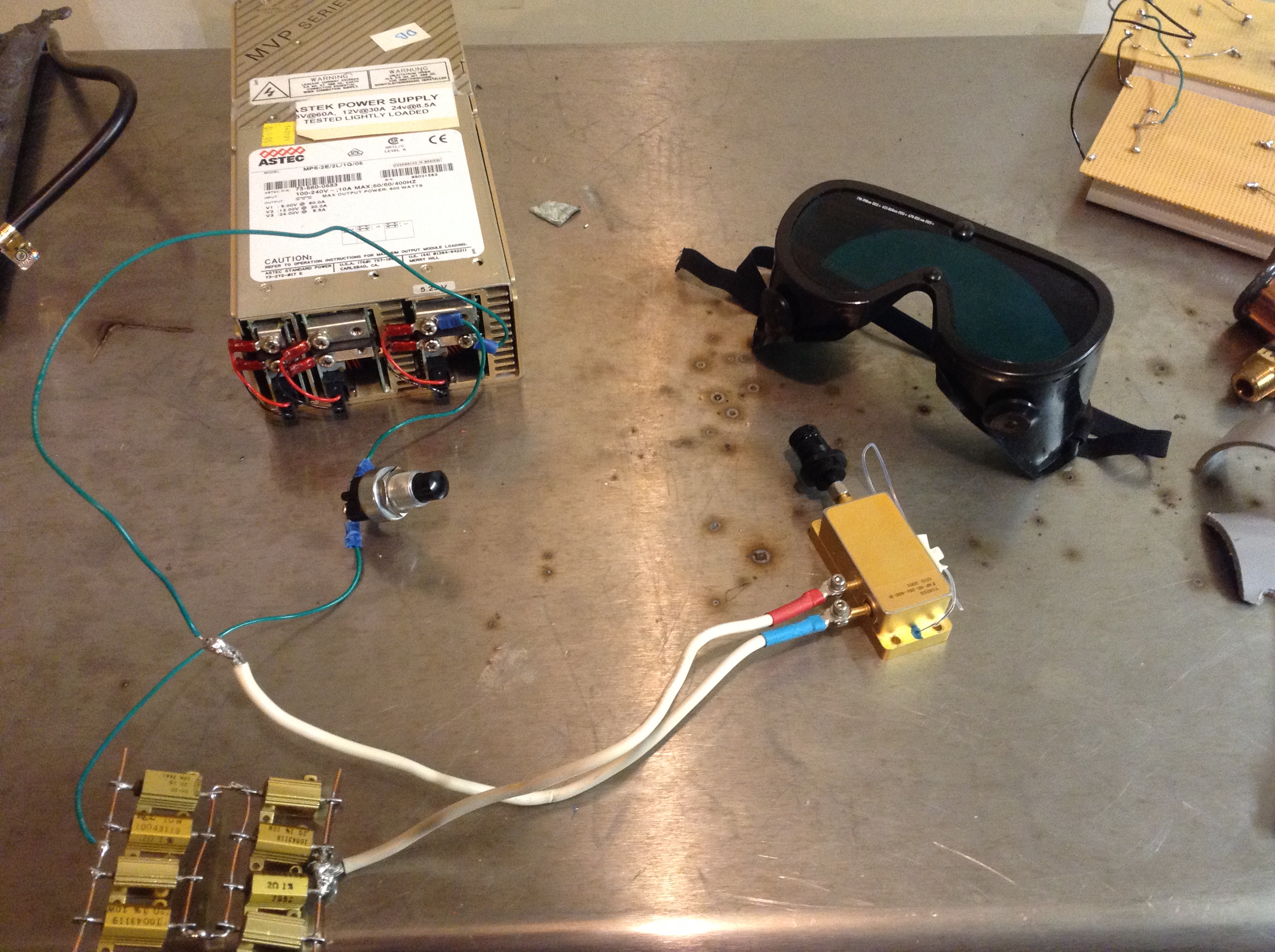
The power supply is the box in the upper left. The laser is the gold box center right with the current limiting resistor array bottom left. Now I wanted to turn it on to see what it could do.
Note the safety goggles in the pic above. These are absolutely required for everyone in the room when this laser is turned on. They must filter the correct frequency of light and be rated in strength according to the laser power. Click here to see this laser in operation. The video shows the laser burning a white cardboard box.
This laser has many dangerous characteristics. Besides the obvious risk of fire, this laser can burn skin. But the greatest hazard is to the eye. The light emitted by this laser is ten thousand times brighter than a laser pointer. You should never look directly at a laser of any power because the eye focuses and magnifies the light on your retina up to 100,000 times. That means a moderately powered laser can instantly burn a hole in the retina causing permanent damage. The injury happens faster than the human blink reflex.
There are a couple more insidious hazards for this kind of laser. First, because it is so bright even a reflection off a matte surface (non-reflective) can cause eye damage. And most dangerous of all, the light is infrared, meaning that it is invisible. A camera is sensitive down in the infrared range so you can see it in the video image, but to the eye it is largely invisible.
It’s a good idea to know what you are doing if you decide to turn on a powerful laser like this. I decided to limit my experiments using this particular laser…
So next I explored what was available in a smaller form factor. When you search these things out, you come up with the popular 445nm blue laser diode used in modern video projectors. There are many hackers who have designed tiny driver boards that allow these diodes to be overdriven to more than 3 watts using a small cell phone battery. What that means is that these lasers can be pushed to run more powerful than they are expected to operate in normal conditions. When the laser is overdriven in this manner, it can easily burn at a distance. So of course I decided to build one. I ordered the parts shown below:
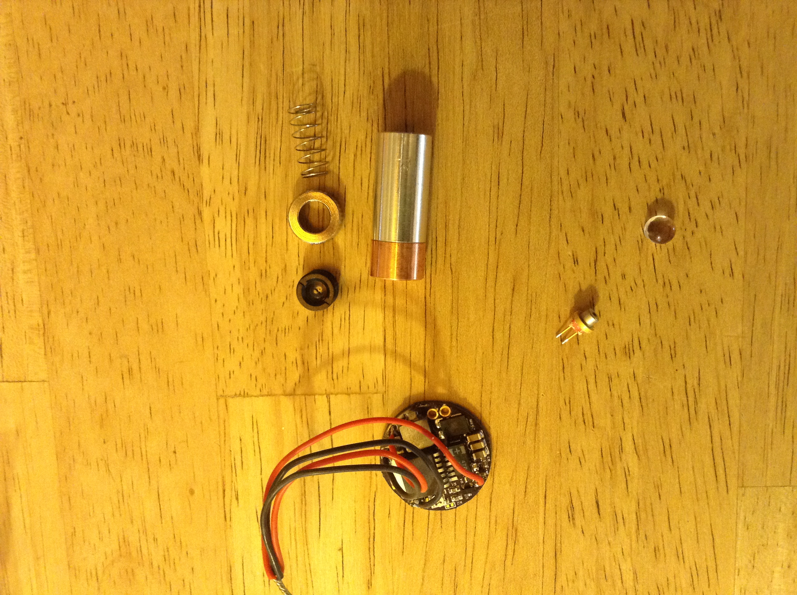
The cylindrical object at the top of the photo is what the laser is mounted in, only about an inch long. The round electronic board at the bottom is a hacker designed charge pump board that delivers the high amperage necessary to overdrive the laser. It’s about the size of a quarter. The laser itself is the small object just to the upper right of the round circuit board.
The small round object in the upper right corner is a glass lens. Normally the laser mount has a plastic lens to focus the beam but because this is an overdriven laser, a glass lens is required so that the lens itself won’t melt.
I got this one put together and tested it (wearing the appropriate safety goggles) and it easily burned stuff at close range. I took a pic of the laser firing at a cardboard box above.
Both of these lasers are the result of high tech manufacturing processes, that is, they are built using semiconductor diodes that did not exist only a few years ago. So perhaps the most interesting laser of all is a home built laser that requires nothing but common material and emits ultraviolet light. I was quite astonished at its simplicity, especially given the difficulties encountered in building the first laser in 1960. In that case it took the intense effort of a corporate research laboratory to develop the first working laser. I wonder how much of history would be different if it was known how easy it was to build a laser like I describe in my next post…
Posted in Nuclear Fusion Reactor, Uncategorized by Mark with comments disabled.
The Fascinating Laser
Burning Blue Laser
I’ve always found lasers fascinating, not only as devices but also philosophically. What I mean is this: Natural laser light does not exist in the universe, yet the principle that makes lasers work, called “stimulated emission,” is a fundamental physical property of the universe. Stimulated emission was first predicted by Albert Einstein in 1917, and the first working laser was built in 1960. Actually, the first device built based on stimulated emission was the “maser” first built in the mid-1950s, but it was based on microwaves and not visible light.
The physics and technology to understand and make lasers gets quite complicated. However, all you need to understand from a philosophical perspective is that no laser light existed in the universe before 1960, yet it had always been possible. Humans revealed an obscure physical law of nature and manipulated their environment to make use of it and wow, how useful it has proven to be in science, medicine, consumer electronics, communication. Almost everyone in this country makes use of lasers many times per day without realizing it.
Laser light makes all these things possible. Nature gave the possibility of generating this light, but not the light itself. It took humans to bring that kind of light into existance.
Up next: Laser experiments!
Posted in Journal, Nuclear Fusion Reactor by Mark with comments disabled.
Because every mad scientist has one in their lab…
trim.3F7DEBDB-50BC-4550-919F-CCA166369F08
click on the link…
Posted in Nuclear Fusion Reactor by Mark with comments disabled.
Power Work Continues…
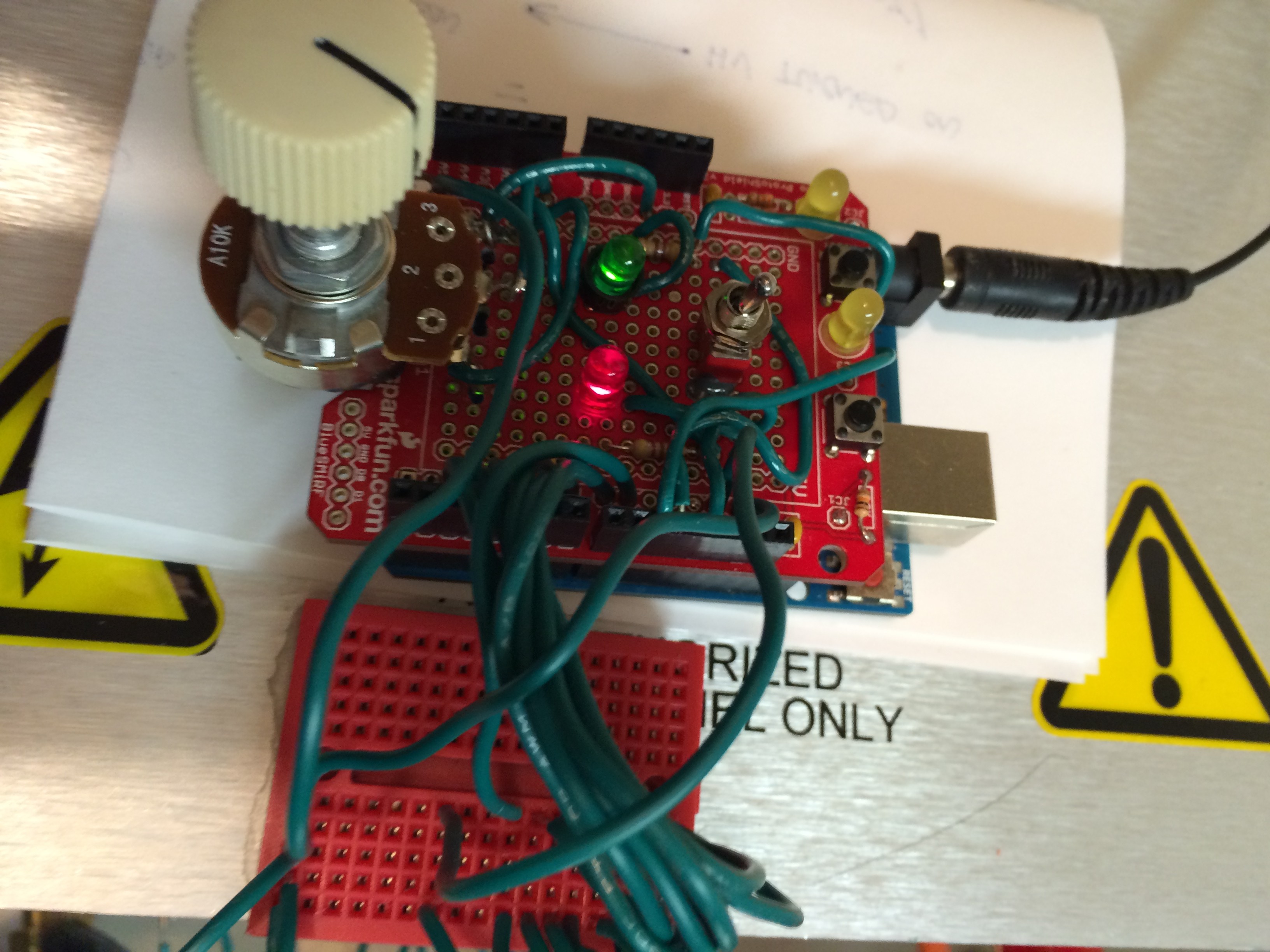
Arduino-based Controller in Operation
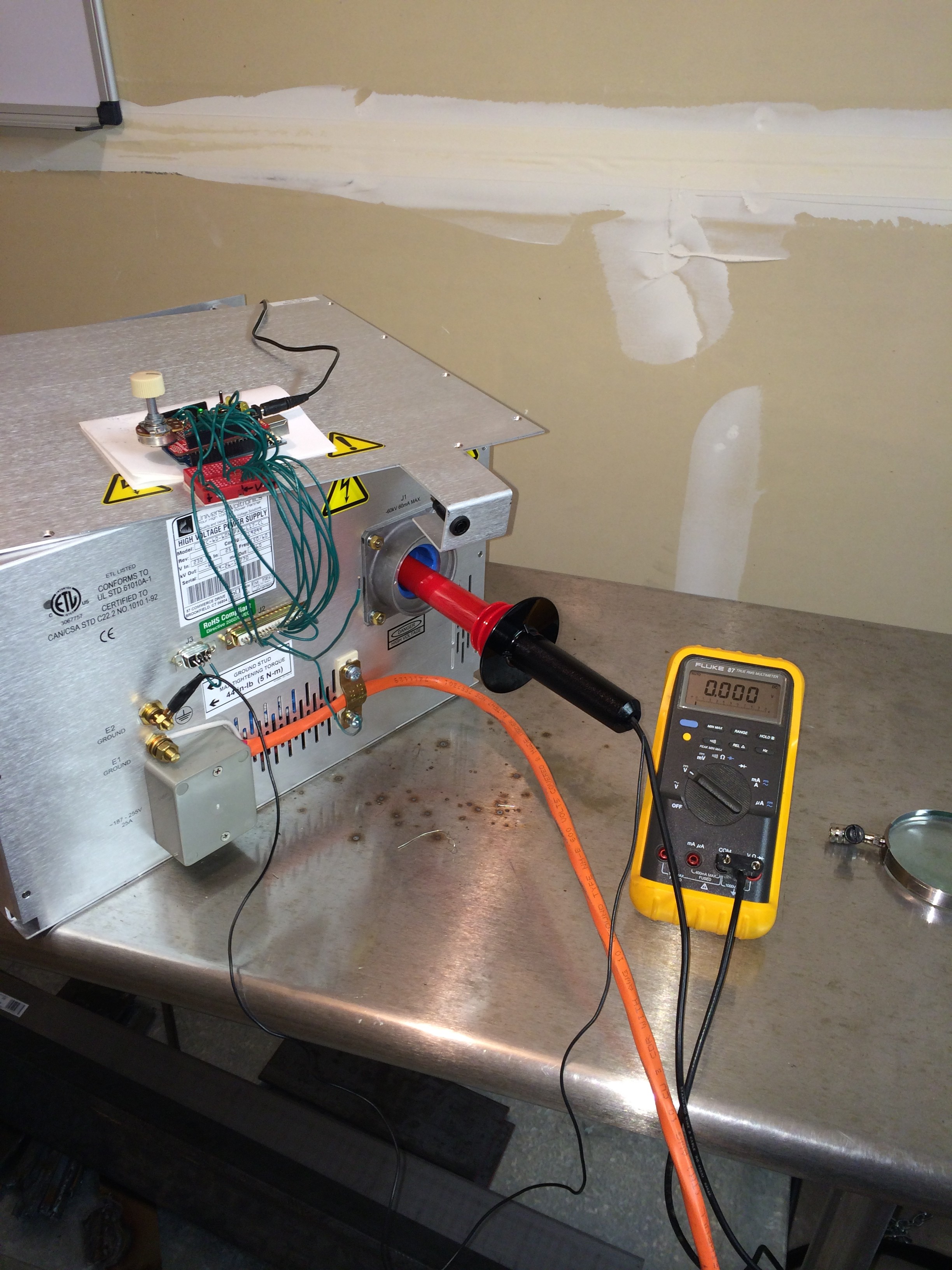
After putting in many hours of work building a controller and deciphering old and incomplete manuals, I have made progress understanding how this box works but unfortunately I haven’t been able to get any voltage output yet. I’ve figured out all the signals and how they work and my Arduino controller, shown above, works as planned. In the picture above, the knob on the left adjusts the level of the output voltage between 0 and -60 kilovolts. On the right is the “operation” switch, basically an on-off switch. There is a green LED that indicates the switch is ON and there is a red flashing LED that indicates the high voltage is ready.
I figured out the three connectors in the high voltage receptacle and connected my high voltage probe to the proper one. Unfortunately, I have not gotten any voltage out despite tinkering with all the input lines in the system. It could be that the high voltage module is broken. I did confirm the internal computer boards are working and the inputs from the Arduino controller are correct. I should be getting some sort of output, but as you can see below, my meter reads zero.
I’ve pretty much confirmed this is a broken supply. Not surprising given how cheap it was. My next choice is to buy another one or build one.
Posted in Nuclear Fusion Reactor by Mark with comments disabled.
Power Test
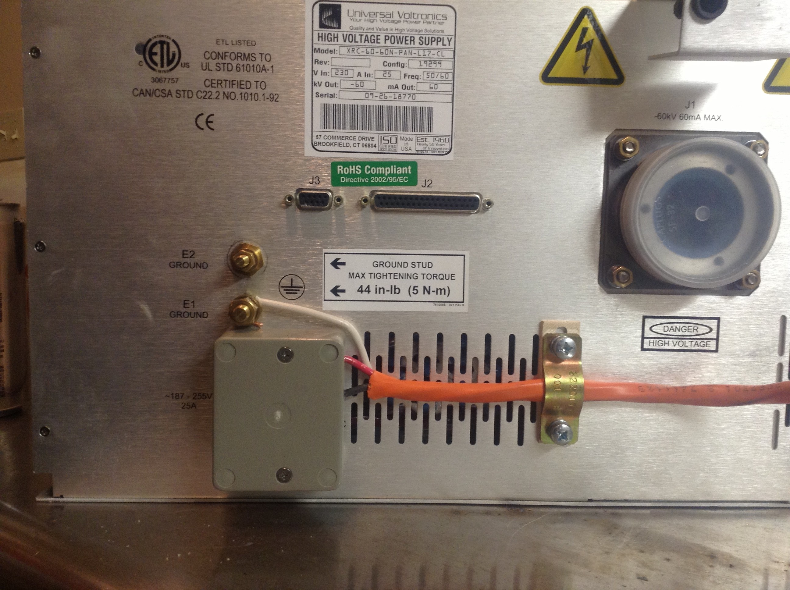 Power Supply Power
So… I finally got my reactor power supply wired up to…power. What I mean is that I wired up a cable and plug from my high voltage box so that it’s ready for the new 240 volt socket in my garage. This box converts the 240 volts alternating current to an adjustable zero to -60,000 volts direct current to be used in my reactor.
I’ve got to admit I was a bit apprehensive about this stage. Though I am an electrical engineer, I have always been leery of high voltage like you find in power circuits. One mistake and you are toast. Burnt toast. Literally. And I mean literally burnt, not literally toast…
Strangely, I have no fear of radiation, another great hazard of this project. I have no idea why. In both cases I have the wherewithal to learn and practice safe techniques, yet for some reason there is a difference. To me, this is like mountain climbing verses caving. Though both require highly similar techniques and abilities in rope work and climbing, I love mountain climbing and will never go caving. I really don’t know why. You couldn’t pay me to go caving. Well maybe you could, depends on the amount. Let’s talk…
Anyway, lethal voltages are something you need to operate a nuclear fusion reactor. This x-ray power supply can generate all the voltage and current I need but it isn’t a complete package. I guess it was pieced out of some laboratory instrument somewhere. I bought it because it was cheap and met my needs, and expected to have to work on it a bit to get it to function, just as I have for every part of this project.
So tonight I got it wired up to my 240 volt plug. I built the orange cable and plug you see in the pics. I turned it on and it works! The pic below shows the first power-on, that box is plugged into my wall socket through the orange cable. No electrocutions or fires either which is always a plus. Now I need to finish the controller so that I can adjust that mega voltage output.
Yikes! 😉
Posted in Nuclear Fusion Reactor by Mark with comments disabled.
Mysterious activities…
Madness!
I have recently been accused by a number of acquaintainces of being a mad scientist! I end the last sentence with an exclamation (!) to emphasize the “madness.” And I quote the word madness to emphasize madness. Which means, if you accept the common stereotype, that madness is more appropriately described as manic. And if that is true, then it may also be true of me. For some reason, this reactor project has had that effect on me.
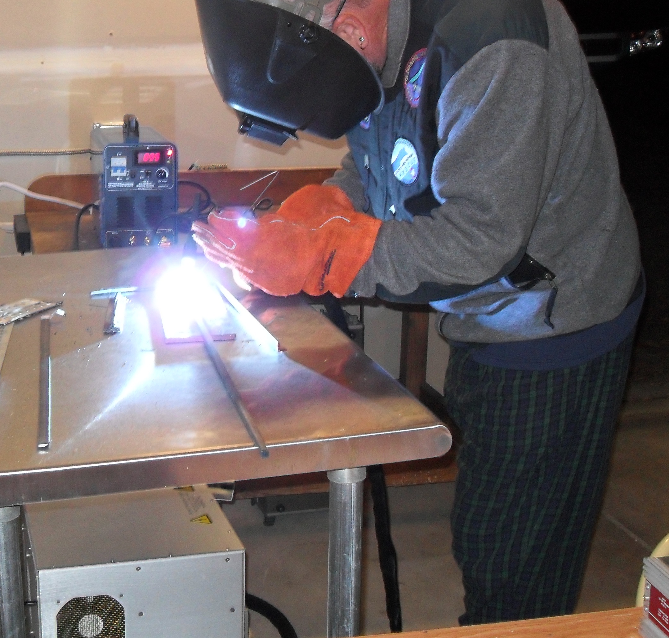
To that end I acquired a TIG welder, pictured above. Why? This is what you need to weld stainless steel, the most common reactor chamber material. I have components that need custom adapters welded to them, the main one being the diffusion pump. I decided to learn to do this myself rather than have a shop do this work. Because that is what a mad scientist would do!
I took a half day welding class last summer. Wow, it was fun! Melting metal with plasma, there are few better (legal) activities for a barely controlled pyromaniac.
My mom, who will read this (hi mom!) might remember when I was about 12 years old attempting to make a radiation shield/neutron moderator. I won’t go into exactly why I was making this, let’s just say I was setting up for radiation experiments… I collected a bunch of lead from fishing weights and car batteries and put it all in a cooking pan. I placed it on the kitchen stove burner and turned it on high. As soon as the lead started melting, I threw in a brick of paraffin. It rapidly melted and smoked furiously, and then caught on fire. Just then, mom came into the kitchen, no doubt drawn by the savory smell of marinading wax and lead. She saw the pan on fire, grabbed a glass of water and threw it on the flaming concoction. It exploded in a fireball of sputtering wax and lead all around the stove. She then grabbed the pan handle and threw it in the sink, extinguishing the fire.
Yow! To this day I have no idea what I told her I was doing, whether it made any sense to her or even if she remembers it. It was just one of the uncountable outlandish stunts I pulled as a kid.
Sorry mom, but as you can see, the madness continues today! 😉
Posted in Nuclear Fusion Reactor by Mark with comments disabled.
Next stage…
 Reactor chamber ready to be assembled
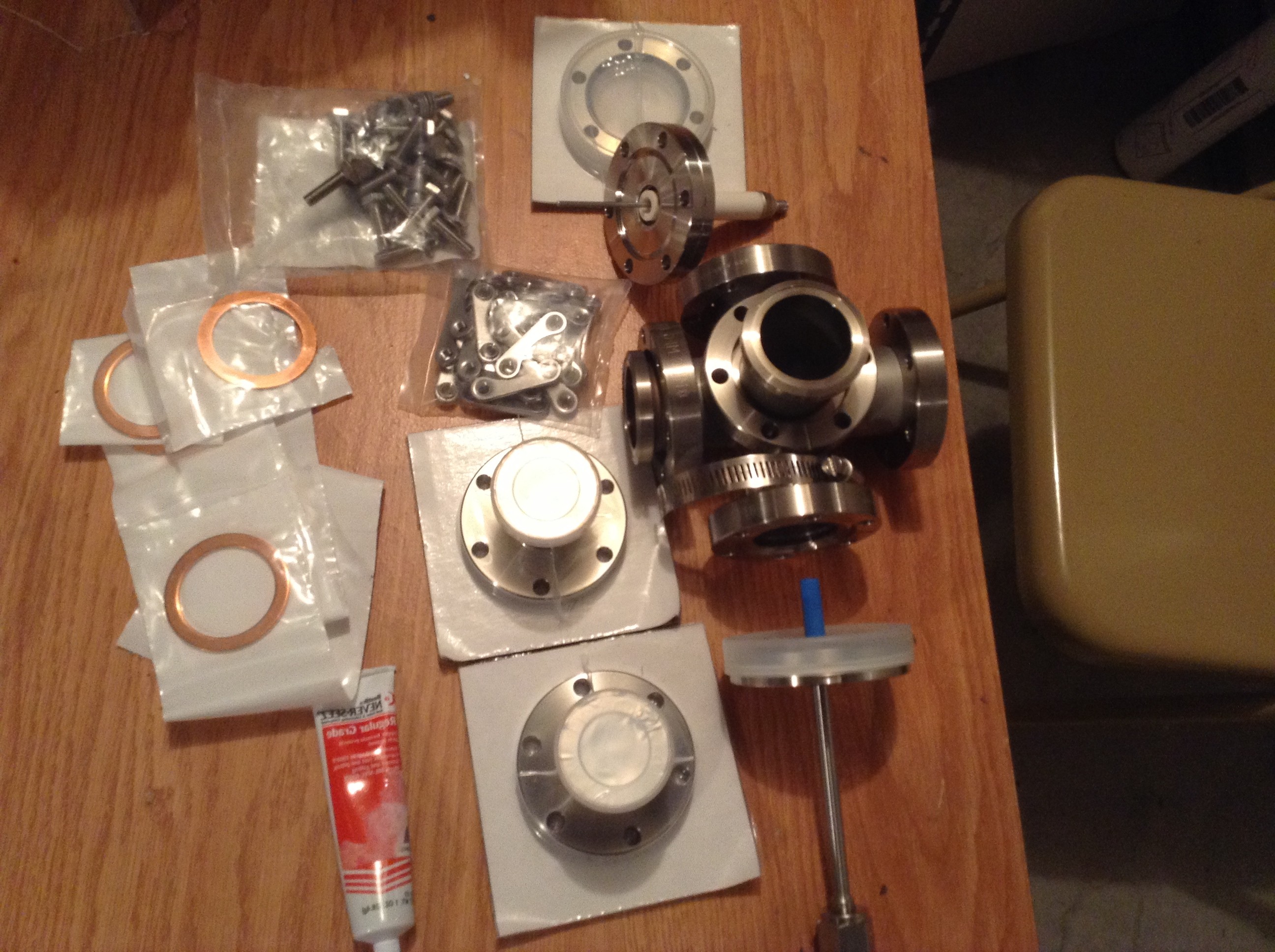
I thought I should post an update to my project since it’s been a while. I had a “demo party” for my beer can reactor Demon I and have disassembled it to make room for the next version. It will be a completely different chamber and power source, and require a bit more instrumentation.
The photo above shows all the parts necessary to put my reactor chamber together. On the right is the 5-way “T” that I am using as my vacuum chamber. The rest of the parts are the attachment adapters that get bolted on to the pipe openings. Also shown is a set of bolts and nuts, copper gaskets and a tube of bolt grease.
 This chamber uses attachment fittings known as Conflat Flanges, or CF flanges. They can be quite expensive but can hold a vacuum many orders of magnitude below what I need, and they are quite common to buy on eBay or order from a vacuum chamber retailer online. They are 2.75 inches in diameter, big enough to work with but not so big they become prohibitively expensive. You can buy huge flanges for big chambers, but the price is likely to be thousands of dollars.
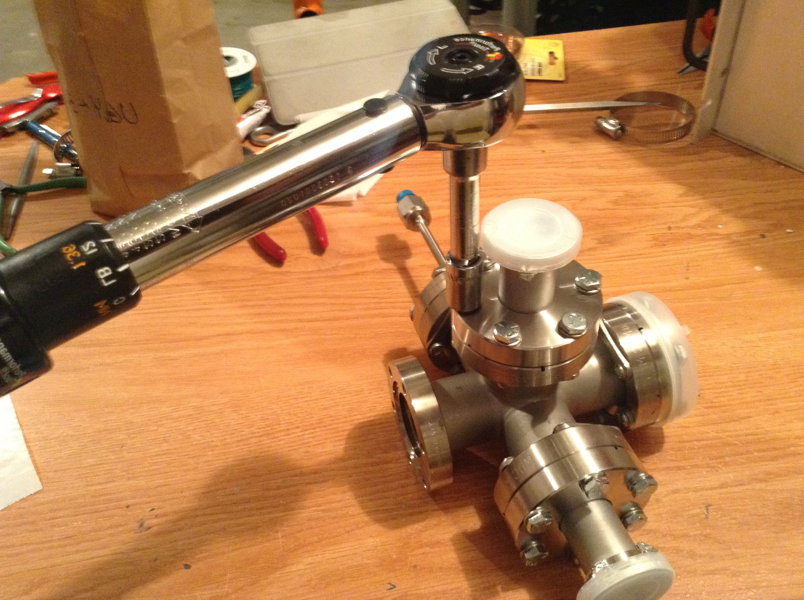
There are 6 bolts on each flange. The proper way to assemble these is to put the copper gasket between each flange and put them together. You then tighten the bolts slowly, cranking a bit on one then on the one directly across from it (shown above). This tightens the flange smoothly all around. You need to use a torque wrench and tighten to 144 inch-pounds for this particular flange. You also need to apply bolt grease to the threads first or the bolts tend to weld to the nuts over time, making it impossible to remove them with a wrench.
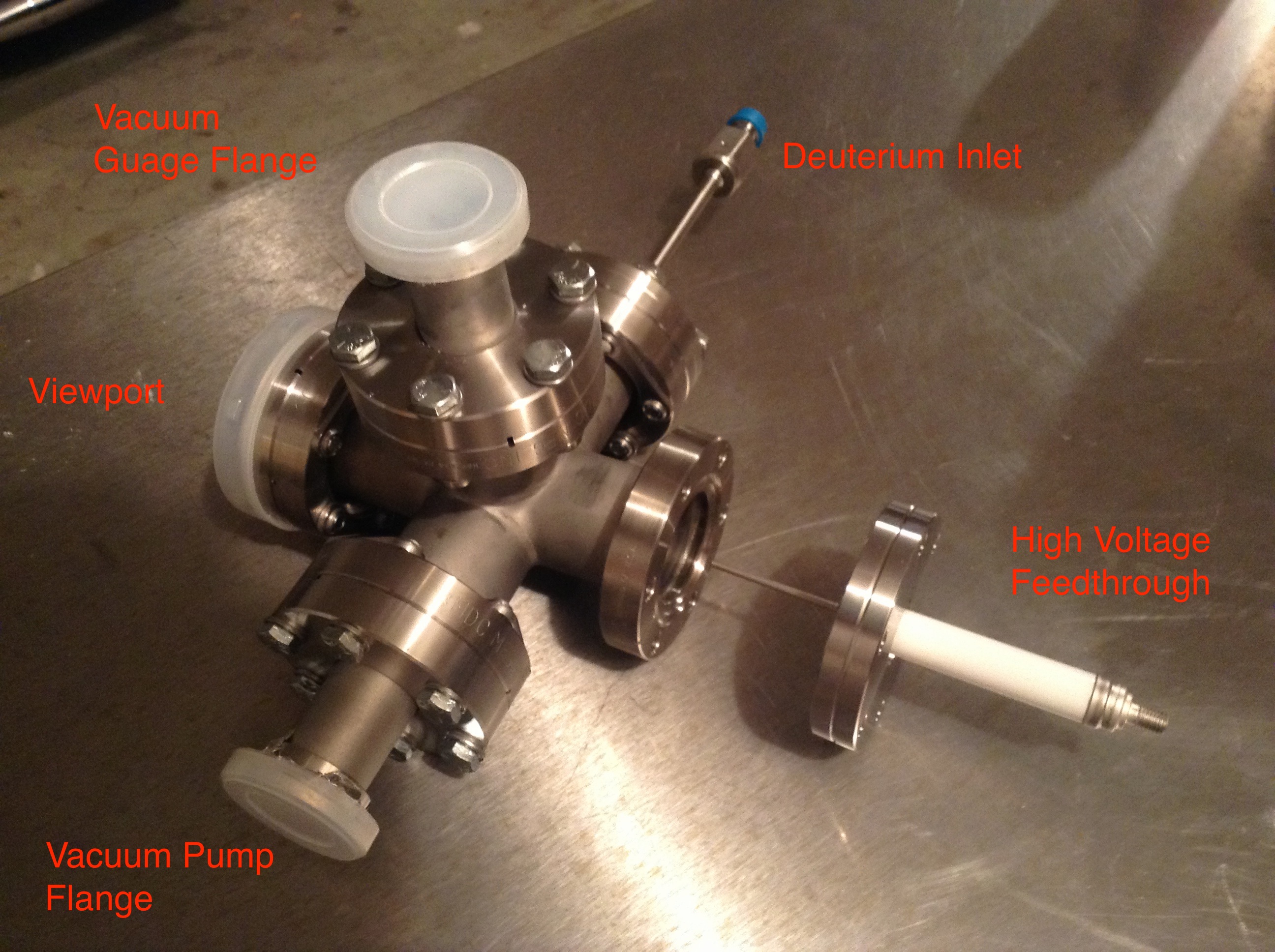 My assembled chamber is shown above with the fittings labeled. The only thing not attached is the high voltage feedthrough because I need to attach the tungsten grid for the core and insulate the stem. This chamber has one new fitting that my beer can reactor did not, the deuterium feedthrough. This will be the inlet for the reactor fuel.
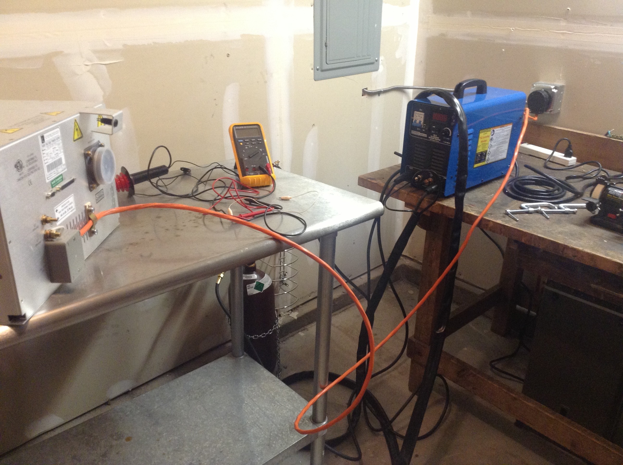
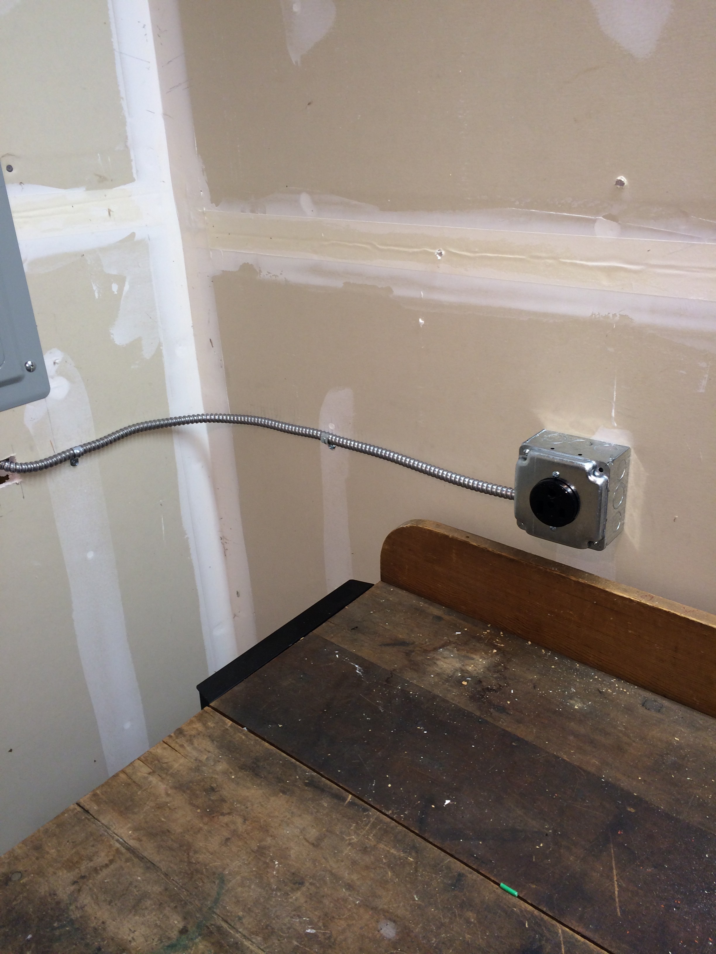
Also, today I had a 230 volt single phase plug installed for my monster power supply, shown below.
Coming Next: Nuclear Instrumentation Modules!
Posted in Nuclear Fusion Reactor by Mark with comments disabled.
High Voltage Controller

Demon Server
You read that right, it is a servant of a frickin’ DEMON! What you see pictured above is an Arduino board with a wifi “shield.” What that means is this: An Arduino board is a hobbyist micro computer controller board that enables you to do all kinds of cool things, like make a wireless high voltage controller. Which is what I’m trying to do..
Ok, let’s step back a minute… A few months back I found a 60,000 volt boat-anchor-of-a-power-supply on eBay. Unfortunately, it did not come with a controller. I can’t adjust or monitor the voltage without a controller. The power supply, which is the size of a microwave oven but much heavier, has a connector in the back with a bunch of pins that are used for signals to control the voltage. Well, an Arduino can easily be modified to apply the proper signals to these pins. But I also want a bit of safety, I don’t want any physical contact between an adjusting knob and the power supply, just in case there is a problem… Like LIGHTNING arcing across the room!
So it turns out you can buy a wireless board, called a “shield” in the Arduino hobbyiest nomenclature, that allows the Arduino to receive and send data over a wifi network. Perfect! In theory. But NOT so much in practice…
It works, I’ll give a lot of credit for that. The problem is that the Arduino hardware and software are open source. This means someone makes something, a board design and software, and then throws it out to the public, open to modification. In theory someone picks it up from there and improves things incrementally until you have a great working product in the end. The BIG, BIG problem with this is that it relies on many people for input and there is no quality control. This technique works for popular projects like wikipedia, but is severely lacking for others. In this case, the most basic things, like readable documentation that could easily have been written by the original designers, is lacking. Big frustration, it took me probably 10 hours to get the thing to work as advertised…
Hey, I’m an Electrical Engineer/Computer Scientist and have done this stuff for decades. I imagine it’s quite a challenge for those who are new to it, but of course that challenge can be part of the fun!
Posted in Nuclear Fusion Reactor by Mark with 2 comments.
Reactor improvements
 Tungsten core with plasma, not the glow at the end of the insulated stem.
Made a couple of improvements on the Demon I reactor so that I can now make many plasma runs without having the core melt down like Charlie Sheen after a 5 day cocaine bender.
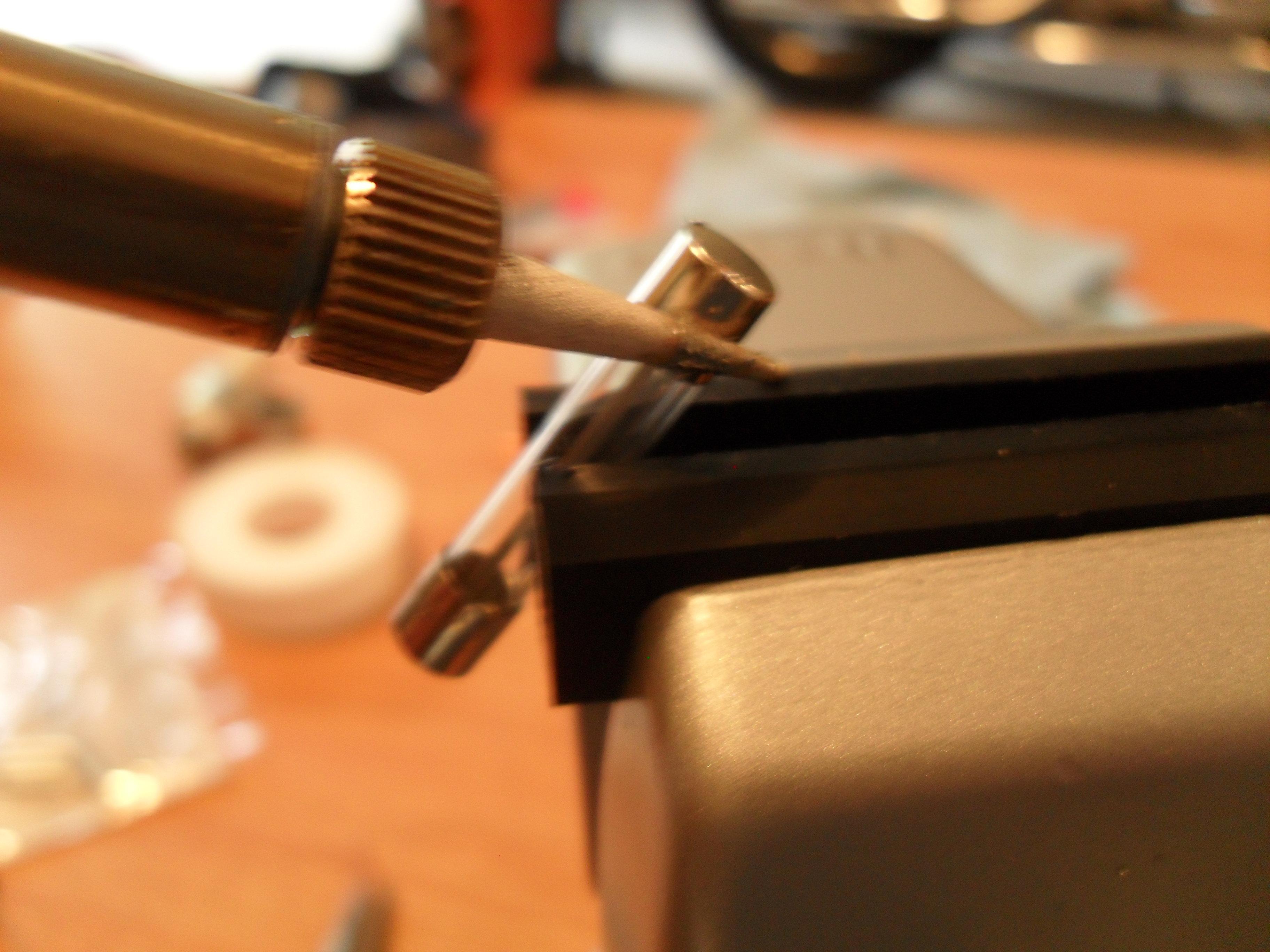
The two major improvements were to insulate the connector stem between the spark plug electrode and the spherical core, and to make the core out of tungsten wire. I obtained 16 feet of 0.01″ diameter tungsten wire on eBay for $12. For the connection insulation, I needed something that could withstand high voltage and temperature, and wouldn’t outgas into the reactor chamber under low pressure. I also wanted something easy to obtain just about anywhere. The answer? A fuse casing. You can easily get glass or ceramic fuses cheap at any Radio Shack or electronics store, or pull them out of a piece of electronic equipment like an old computer power supply.
All you need is the casing so you have to remove the ends and internal fuse wire. This is easily done by heating up the end caps with a soldering iron and popping them off as shown in the sequence below:
The fuse fit perfectly over the connector and helps prevent it from overheating. I also got another vice to make a more sturdy mechanical support for the chamber. And I was able to fix the current meter on my power supply so that I can now measure the input current, voltage and pressure. All of these are needed to characterize how well the reactor is performing. Below is the new setup in operation.
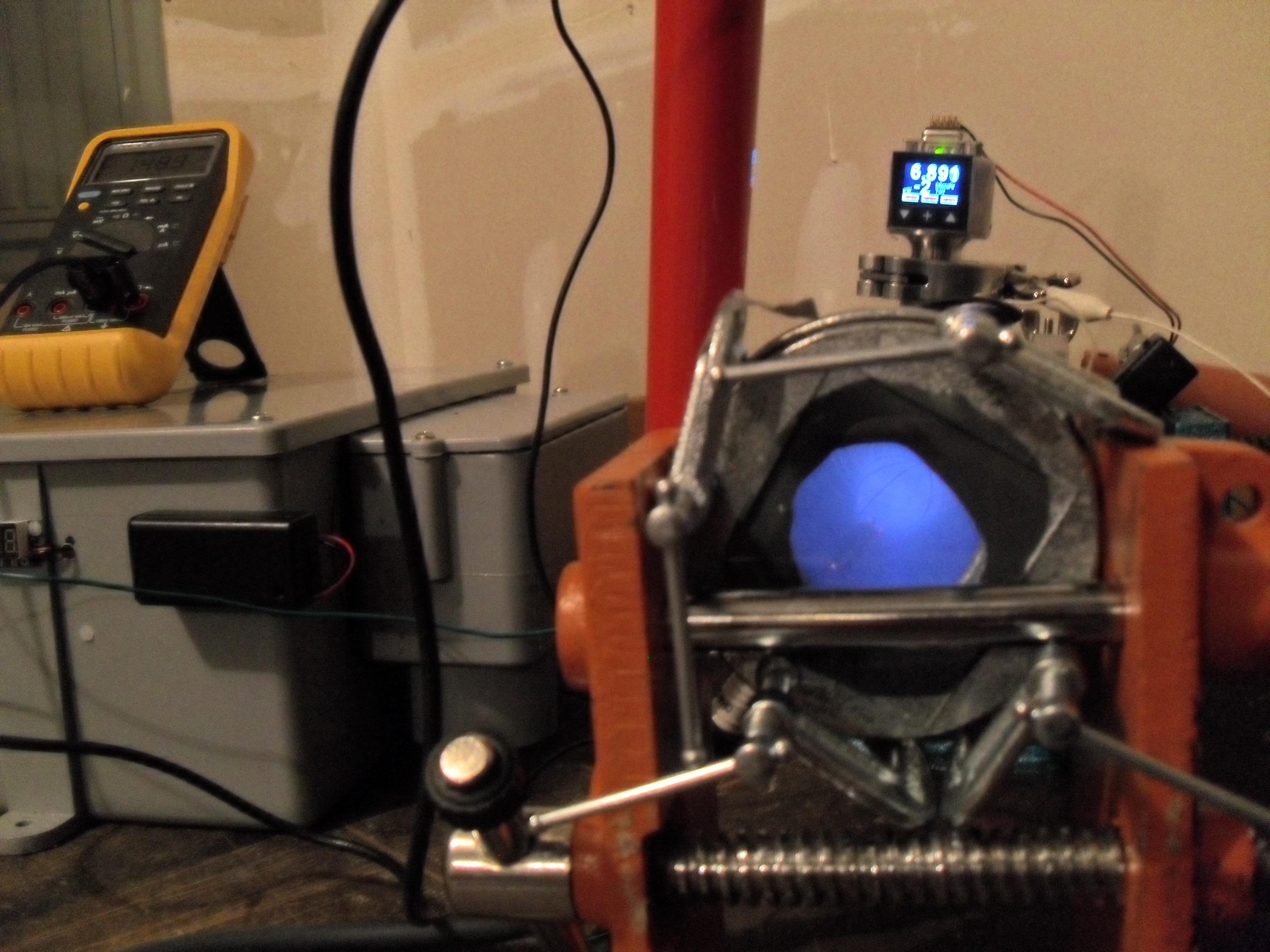
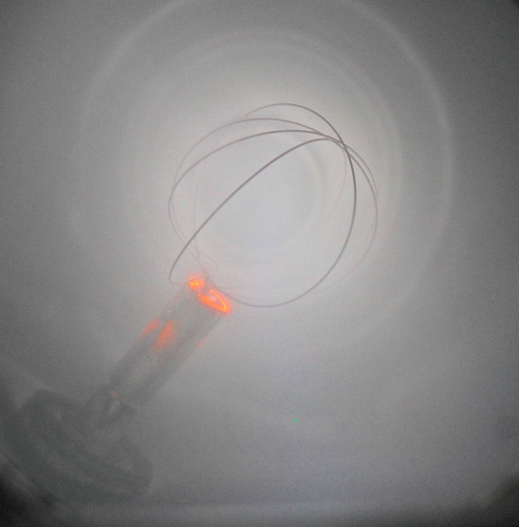
So the cool thing about these improvements is that I can make multiple, long runs without having to rebuild the core. During one run I was able to get a photo of an electron beam streaming out from the center of the core to the chamber wall. This is a normal phenomenon and in a well-built system with a higher vacuum you will see many of these streams emanating from the core. Shown below:
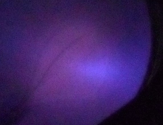
The beam isn’t well defined in this fuzzy photo but it shows up as the blue glow just right of center. To the naked eye it is very well defined and obvious but my camera isn’t able to catch it using the automatic settings. I’ll have to experiment and try to get a better pic.
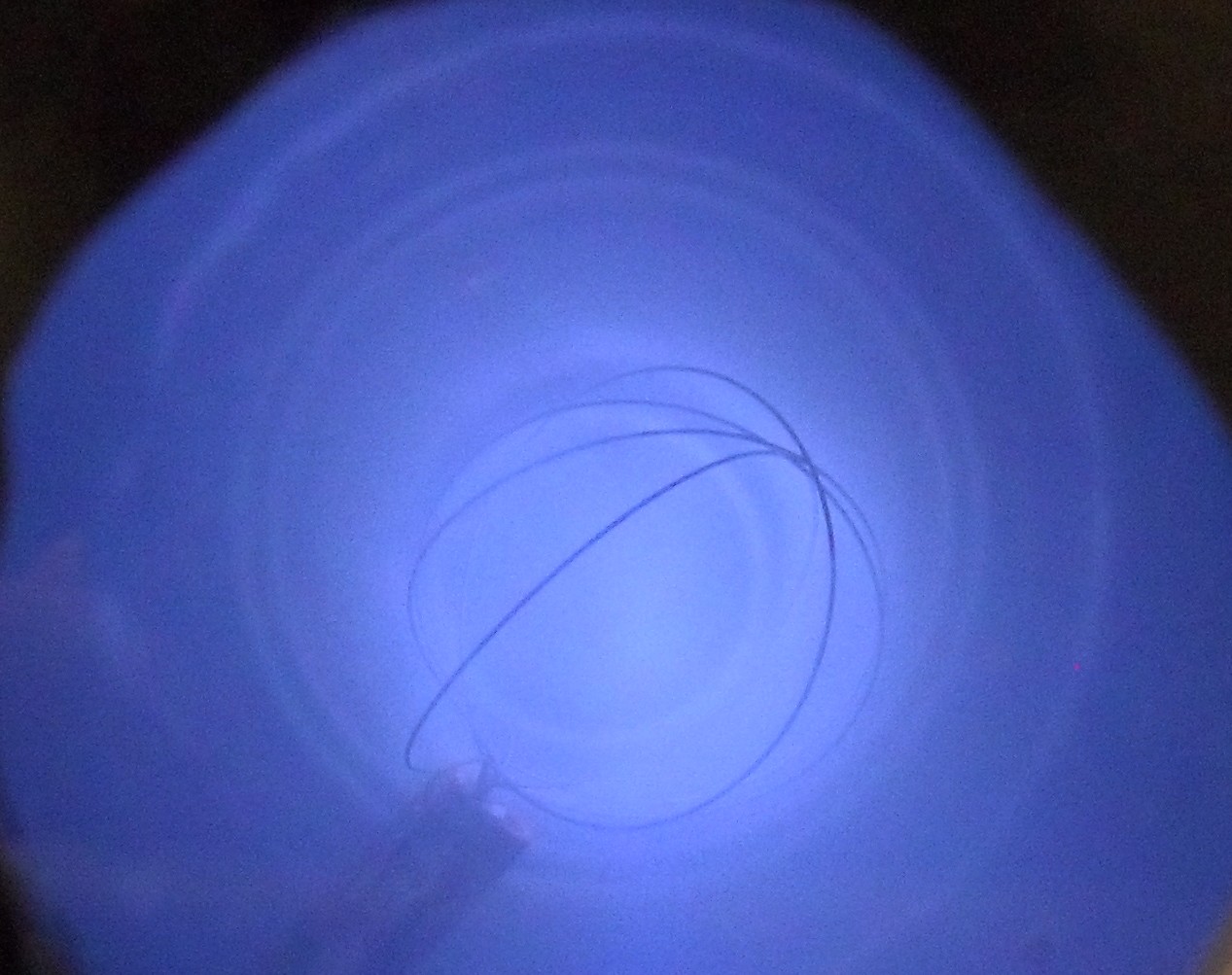
Finally, I was able to get a good photo of a great confined plasma, meaning much of it is centered inside the core grid. This is a requirement for a reactor actually performing fusion. Pic at the end of the post.
The biggest improvements I could make now are to get a better vacuum, but even if I did I wouldn’t get much more than a better confined plasma. The next step is to work on my neutron generating reactor, the one that will actually perform fusion. I’ve got a bit of work to do on that project, but I should have most of the hard-to-obtain parts in house at this point. I’ll get to that project in a couple of weeks, in the meantime I’ll be on a completely different type of adventure. Updates to come!
Posted in Nuclear Fusion Reactor by Mark with comments disabled.