Demon One!
Drink deep, or taste not, the Plasma Spring! – Jeff Goldblum in “The Fly”
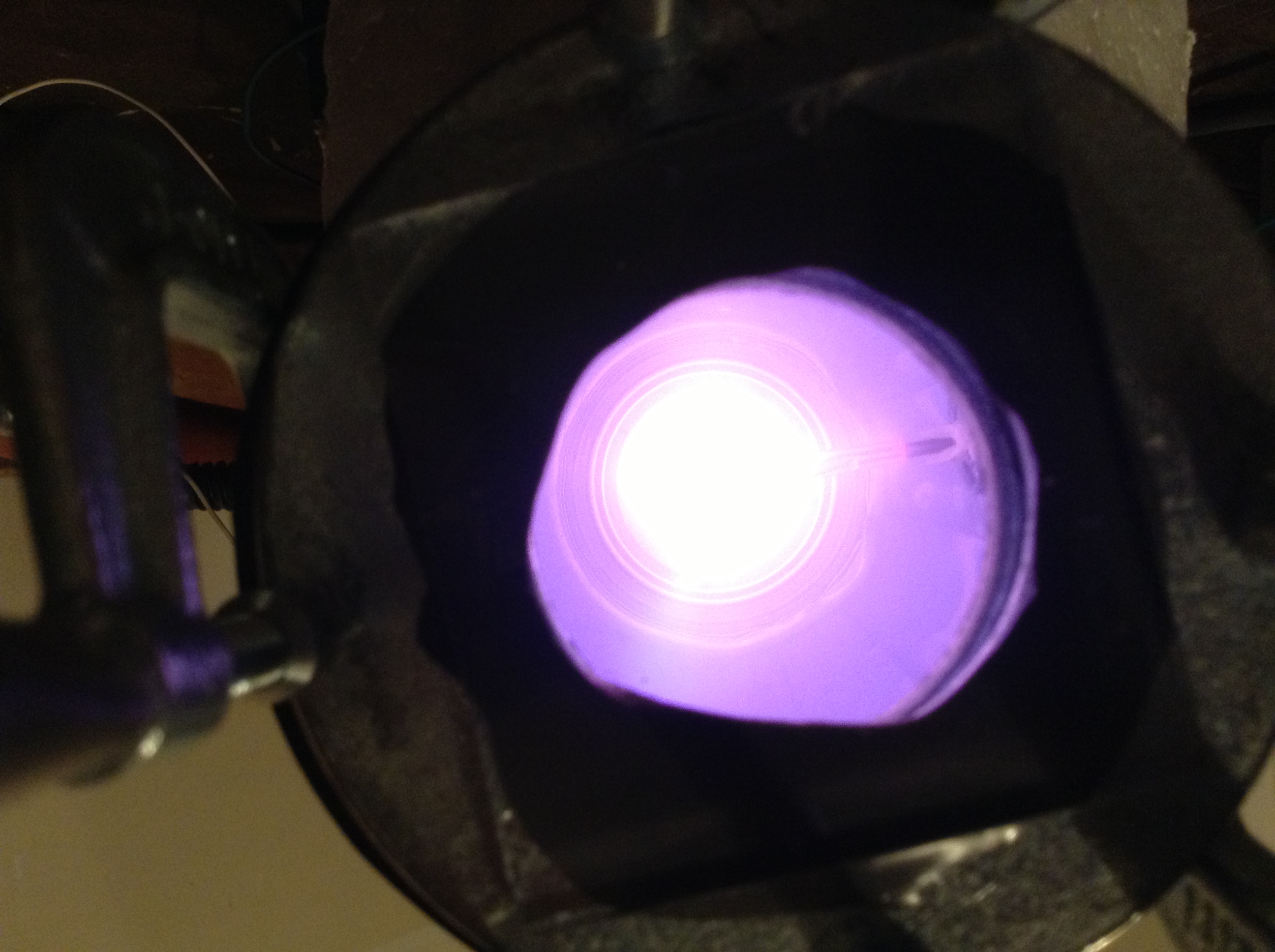
Success! On my first run ever, tonight at 8:15 p.m., I created confined violet plasma in my beer can reactor (pic above). This is the first major milestone on the path to fusion. I christened my first reactor Demon I. The name has significance which I will explain later in this post.
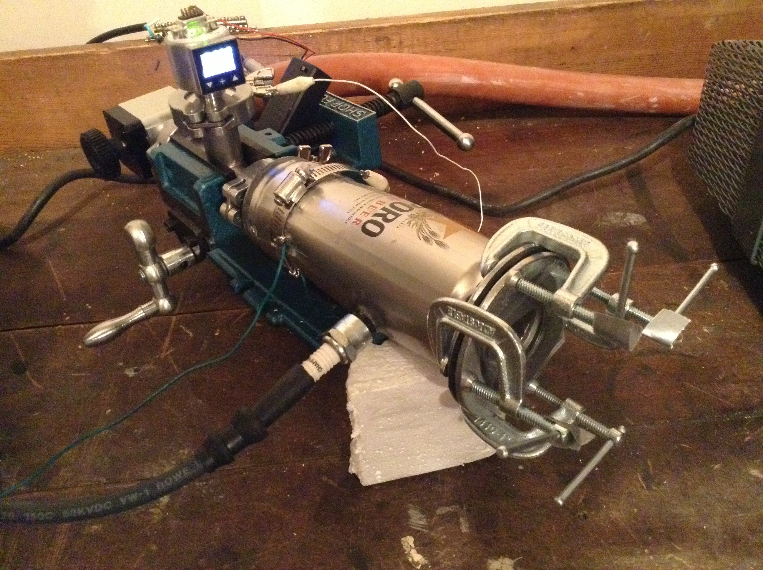
The setup is shown below. Click or double tap on the photo to get a larger version:

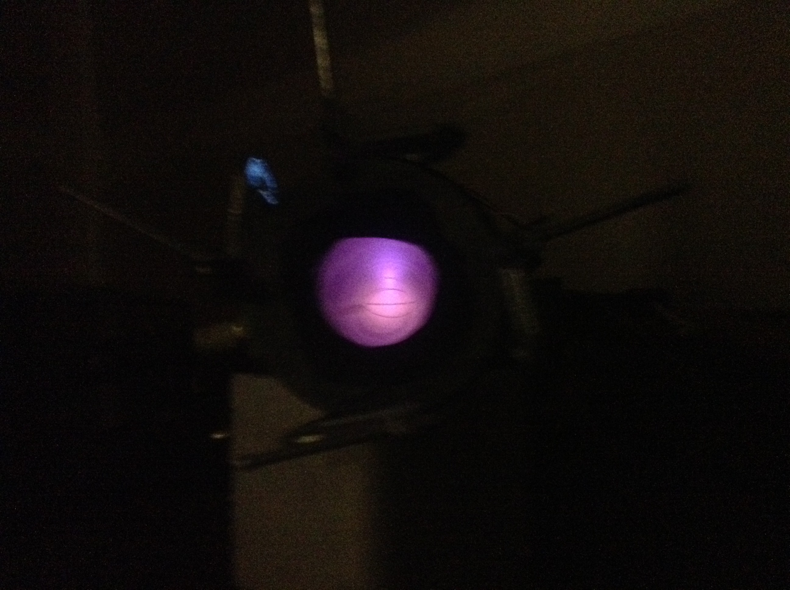
I took some photos with my ipad but they showed up kind of funky. Below is my proof of a confined plasma. What I mean by that is the plasma was confined in the spherical core of the reactor, a requirement for this type of device. The photo is quite fuzzy but you can see the wires of the spherical core. The plasma ball was plain as day to the naked eye, with an electron stream out of the ball to the top of the chamber:
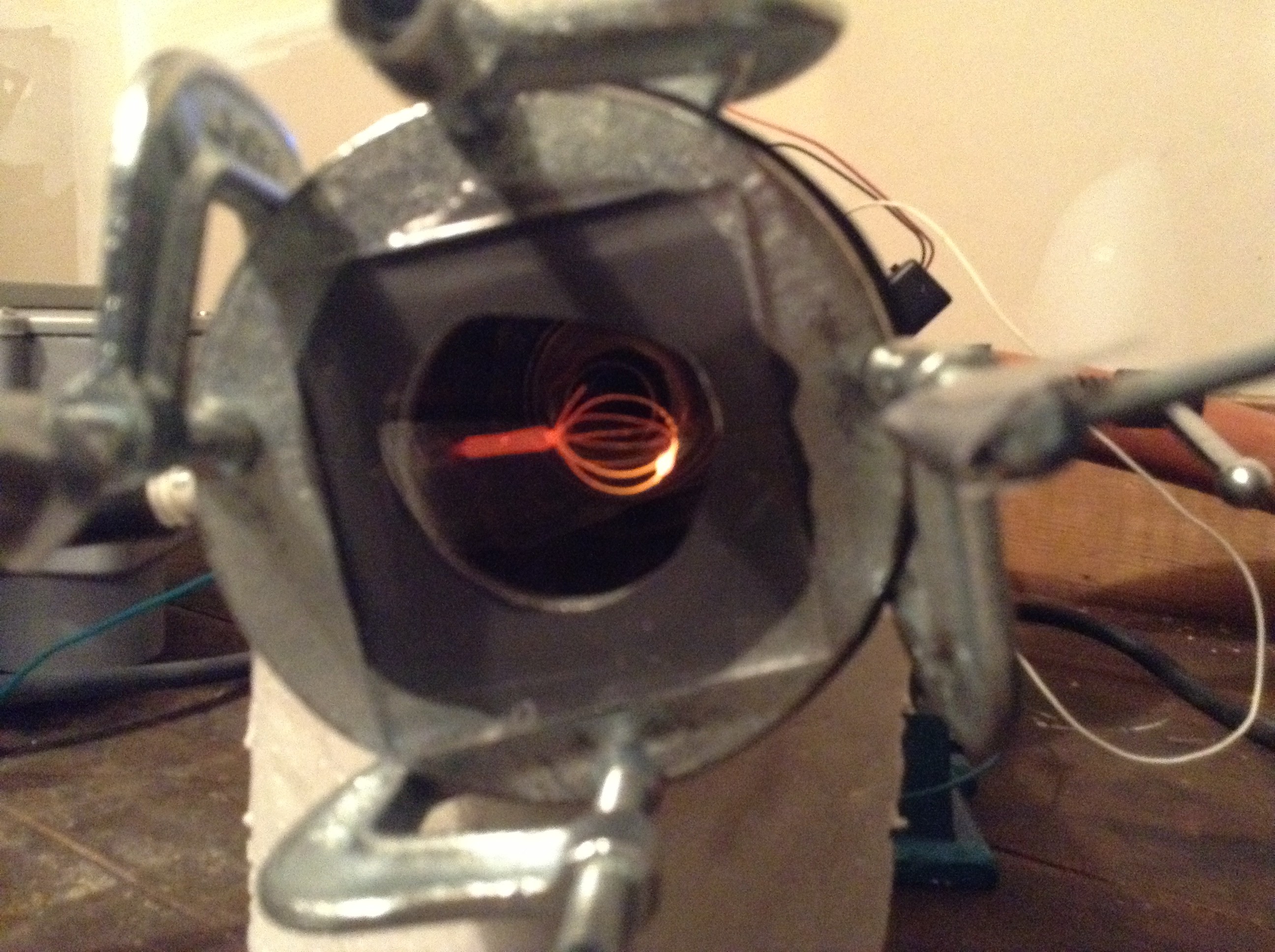
I took a pic of the chamber just prior to the first run:
My current meter was DOA and I didn’t set up a voltage measurement, but I can approximate that the voltage was in the 5000-6000 volt range based on where the variable transformer was set. The vacuum chamber pressure varied between 100 and 130 millitorr. As I increased the voltage, the pressure rose slightly due to outgassing. As I increased toward the max voltage, I could see that the grid was disintegrating. I ended the run and took a photo of the hot grid below:
A beer can has a polymer lining to keep the beer from reacting with the metal can. This turned out to be no problem for this run. As a matter of fact at the end of the run I did not notice any degradation of the can lining at all. Can’t say the same for the reactor core, it melted big time:
I thought the wire was stainless steel but it appears to be copper which has a lower melting point. That would explain why I had a core meltdown at such a low voltage…
Why call it Demon I? A couple of reasons. The first is to inspire an antithetical view to a device that on the surface seems really cool. I could call it inspirational positive names such as Star Chlid or New Dawn, but the reality is that all technology is used for good and evil, inspiration and disdain, freedom and oppression. I think Demon I is really cool simply because this is what I was able to create in my garage. On the other hand, that doesn’t make it inherently good. Nor is any “cool” technology inherently good. It isn’t inherently evil either. It is what it is. Think about the Manhattan Project, the program to develop the atomic bomb in WW II. For the scientists involved it was the opportunity of a lifetime to make something that had never been done before. We all know the results. Were the scientists evil? No, they were just doing what they do, and the technology is not good or evil, it is simply a revelation of the way nature works. The Manhattan Project is a stark example that can be extended to all technology, period.
The second reason is I wrote a book called Forty Demons…
😉
ANYWAY, drink deep of the plasma spring!

Posted in Nuclear Fusion Reactor by Mark with comments disabled.
How to build a vacuum chamber…
 Start with a beer…
Here is a list of easy-to-find parts necessary to build a nuclear fusion reactor and where to find them:
- Beer can (liquor store)
- Oil burner igniter (online spark plug store)
- Threadsaver sized for the spark plug (hardware store)
- Small lexan or polycarbonate sheet (hardware store)
- Two 1.5″ zinc washers (hardware store)
- 6″x6″ thin neoprene sheet (hardware store)
- Four 1″ C-clamps (hardware store)
- Small portion of JB Weld or similar epoxy (hardware store)
- Thread seal tape (hardware store)
- Large gauge wire crimps (Radio Shack)
- Stainless steel wire (Radio Shack)
- KF25 weldable nipple (eBay or scientific vacuum company)
Total cost: $79.40
And actually, it’s much less than that, probably well under $50 due to the fact that the smallest amounts of these items is much more than required for the reactor. The most expensive item was the threadsaver, basically a small sleeve for the spark plug, because they only come in boxes of 8 and you only need one.
How do you build the chamber? Well, first you get the proper beer can. Aluminum won’t do. However, Sapporo beer cans are made out of corrugated steel and are surprisingly strong. You can get them almost anywhere that sells Japanese beer.
The next thing you do is empty the beer. My friend Anna asked, “do you pour the beer out in the sink?” Well yes, that is one method. Another method would be to pour the beer into your mouth and drink it.
When the beer is empty, drill two holes of proper size, the spark hole (below, top) and then the vacuum feedthrough hole (below, bottom).
 Next, cut the top off. This is more difficult than you might imagine, I used some small tin snips and needle-nose pliers to remove the top (pic below). It is much more difficult to do this on a steel can vs aluminum and you should wear proper gloves unless you like multiple, deep cuts on your fingers. This will be the viewport.
 After you’ve finished drilling and cutting, clean out the can with soap and water and let dry. Next, cut the neoprene in the shape of the zinc washer to be used as a gasket, then cut a small square from the lexan sheet (below).
 Next step is to epoxy the vacuum and spark plug feedthroughs. Epoxy one of the zinc washers on the viewport end. Epoxy the lexan window to the other zinc washer (see below).
During this process, don’t forget to keep the supervisor happy:
 Wait until the epoxy sets, about 24 hours, and then add thread sealant tape to the spark plug and crank it in tight. Clamp together the gasket and window flange to the viewport end.
Now you’re ready to test the vacuum!
Attach the chamber to a vacuum pump that has an appropriate vacuum gauge (see two pics below):
 Turn on the pump and wait. After several minutes, my chamber read below 70 millitorr (last pic below). That’s good enough for the first step, a “demo” reactor that will generate an air plasma. Cool!
Next: Hooking up the power !!
Posted in Nuclear Fusion Reactor, Uncategorized by Mark with comments disabled.
Building the Reactor…
 The Reactor “Core”
I decided a couple weeks ago that the best approach to building a neutron-generating reactor is to first build a kind of scale model, known in the amateur world as a “demo” reactor. It is basically an air plasma reactor that doesn’t actually produce fusion but does require high voltage and dealing with a vacuum chamber. Since I have little experience with HV and no experience with vacuum chambers, I need to get up to speed on the nuances of both. Basically, this first model has all the features of a fusion reactor but doesn’t require as much skill, kind of like learning to walk before trying to run.
I spent many hours at the hardware store last week seeking out parts and then many more hours experimenting in the garage to come up with construction methods. The photo above is the inner grid. This is the reactor core where, in theory, the fusion takes place. The shape is important, it should be spherical or at least cylindrical. It is made of four loops of stainless steel wire held together with a wire crimp. The other end will be crimped to my high voltage feedthrough.
And what is a high voltage feedthrough and why do you need it? The reactor works by applying a very high voltage between two electrodes. The inner grid is the negative side. In my design, the positive side is the metal vacuum chamber wall. The negative voltage must get through the wall without shorting out, it does this by going through an insulated feedthrough. The feedthrough must also be vacuum tight.
 Seems like a tall order, but this is exactly what a spark plug does. It feeds a high voltage through the metal car engine casing into the cylinder, and it forms an air-tight seal. So I bought a spark plug. Unfortunately, the electrode on most plugs does not protrude enough to attach my grid with a wire crimp, so I bought an oil burner igniter plug, shown at right. These can easily be found on the internet and cost only a little more than a common spark plug.
You can see by the photo that the electrodes are much longer. However, the thread size is exactly the same as most spark plugs.
 Like everything in this project, it can’t be used right out of the box without modification. The ground electrode must be cut off and actually the central electrode is too long for my design, so I had to cut a bit off as well, pictured on left.
My current plan is to make my reactor fairly small, mainly because buying a large vacuum chamber is amazingly expensive but also because I want it to fit in my garage for now. So the objective for this first chamber is to be approximately the same size, that way I can get experience dealing with smaller dimensions. For instance, the grid at the top is less than an inch in diameter, which will be the size of the grid in my neutron generating reactor. It ain’t easy dealing with such small structures…
In other news, all kinds of vacuum parts have arrived. Unfortunately I am still waiting for parts for the vacuum pump. In the meantime, I was able to test out my stand-alone gauge connected to what will be my backing pump isolation valve, pic below (reading atmospheric pressure)…
Next: The chamber being constructed, made from a common object. Can you guess what?
Posted in Nuclear Fusion Reactor by Mark with comments disabled.
Power supply tested…
 That’s 8,950 volts!
Finally got to the testing phase of my power supply design. The smoke test was successful (in that there was no smoke) and the max voltage reading was close to 9000 volts negative, which means the power supply is working as designed.
This power supply converts normal house AC voltage to something that can generate fusion in the reactor. The power can be varied from zero to maximum voltage by using a component called a variable transformer. The variable transformer takes input from the wall socket and outputs to a box that steps the voltage way up and turns it into DC current. The box looks relatively simple, shown below:
 Looking down, the box contains a blue neon sign transformer on the right. This is the thing that steps up the voltage way up. On the left you can just make out some high voltage microwave diodes that look like little black rectangles. Just to the right of the transformer is a gold colored high power shunt resistor for measuring current. The cylindrical object in the upper left corner of the pic is the variable transformer. The diodes rectify the AC signal, meaning they turn AC into DC. Diodes allow current to flow one direction and not in the reverse direction. If you design the circuit correctly, you end up with a high voltage negative DC supply, exactly what you want to produce fusion.
Believe it or not, this circuit is extremely simple and easy to understand and make for those with the most basic knowledge of electronics. What makes this device unique is the extreme high voltage. This is not an every-day home electronics project, these voltages can be instantly lethal if not managed correctly. Just about every aspect of this device has to be designed with that in mind if you want to maintain a safety factor.
The first design rule is to have no exposed high voltage that could be touched by accident. To do this I needed to come up with an enclosure, but even this isn’t as simple as it sounds. You need a material that can insulate and won’t break down in a high voltage environment. This is what I mean: Air is an insulator. That’s why you can walk near a wall socket and not get electrocuted. But if there is a big enough voltage difference, air “breaks down” and becomes a conductor, for example, lightning. As a matter of fact, air is not one of the better high voltage insulators, it can break down in as little as 20,000 volts per inch. That sounds like a lot of voltage but note that my power supply is nearly 9000 volts, meaning that it could arc across a little less than a half inch of air. This means just getting close to the supply without touching it could cause electrocution.
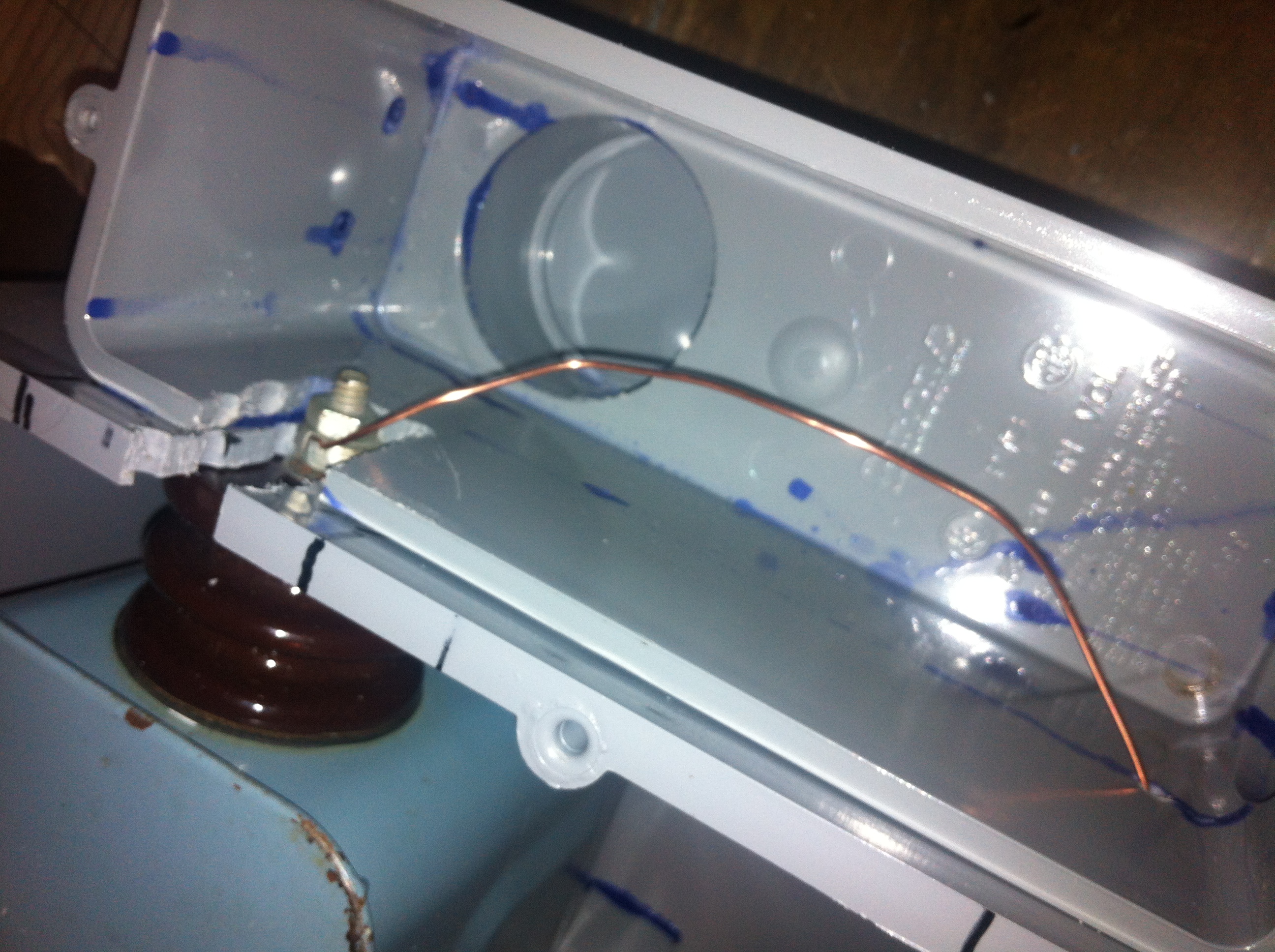 Wood and rubber are not good insulators for these high voltages. However, it turns out that polyvinyl chloride, or PVC, is an excellent insulator with a high dielectric breakdown. So I constructed a supply enclosure by epoxy-ing together PVC junction boxes I bought at a home improvement store. I then cut and drilled to accommodate the transformer and other components. As you can see in the pic at left, the wiring internal to the box is bare. This is intentional as ordinary wire insulation is inappropriate at high voltages, it can potentially break down and catch fire at these voltages. As long as it is enclosed during operation, there is no danger of electrocution and the wire layout is intended to prevent arcing between components.
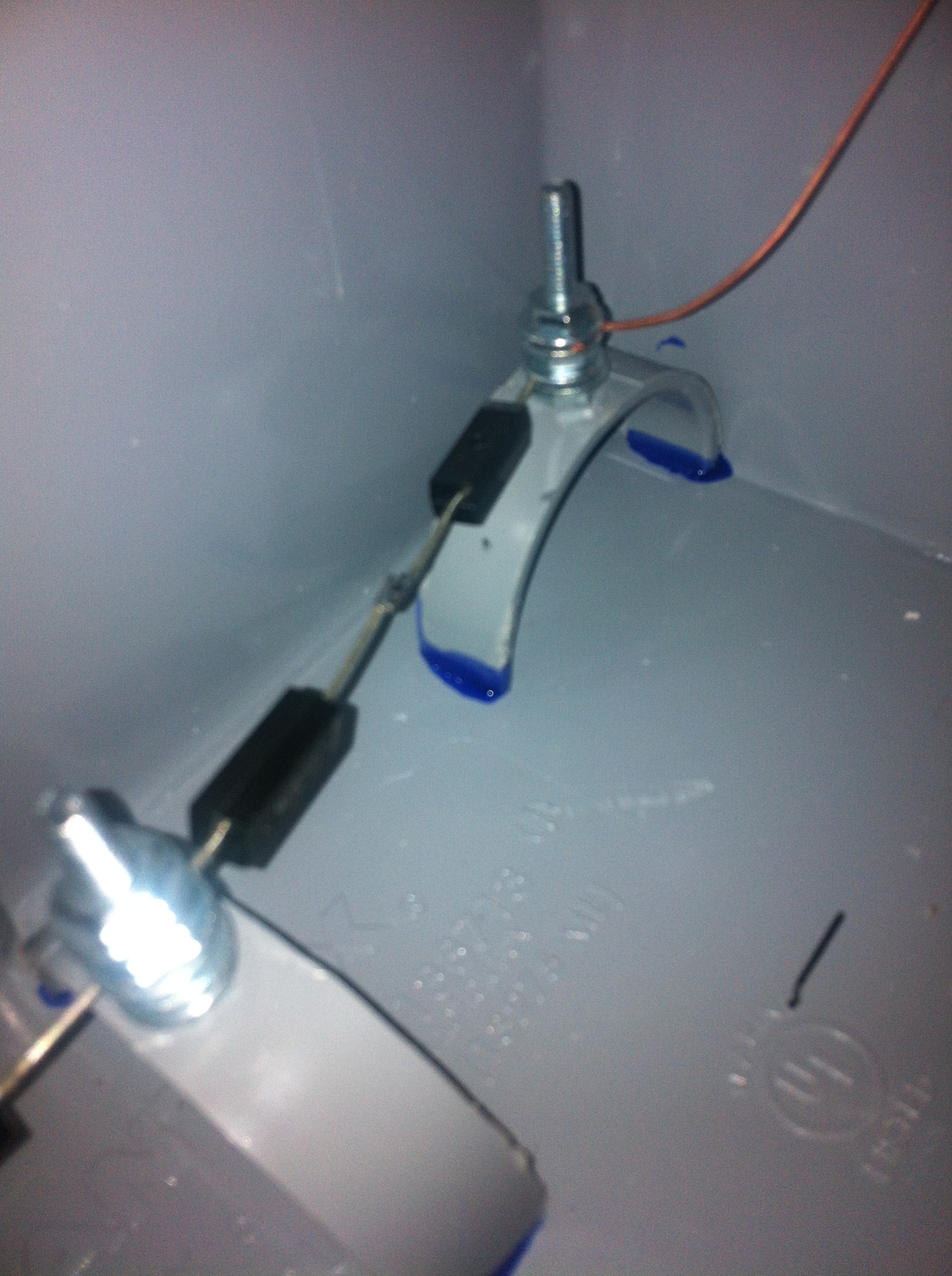
The (poor quality) pic on the right shows one half of the rectifier, two high voltage microwave diodes wired in series to screw terminals on PVC standoffs that I epoxied to the case. The standoffs provide a base for the screw terminal without having to drill through the case. The dark blue streaks you see in the photos is the color of the epoxy. The two diodes on the right are half of the rectifier, there are two more wired to the other side of the transformer. Normally it only takes two diodes to make a full-wave rectifier, but again because of the very high voltages being generated, you need a special setup to prevent the diodes from failing. These are 12,000 volt rated microwave oven diodes, placing them in series gives you a 24,000 volt “rating” that give you an operating margin for safety. Finally, the diodes must be arranged so that they produce a DC current that is negative with respect to ground. This “negative hot” quality is necessary for this type of reactor design.
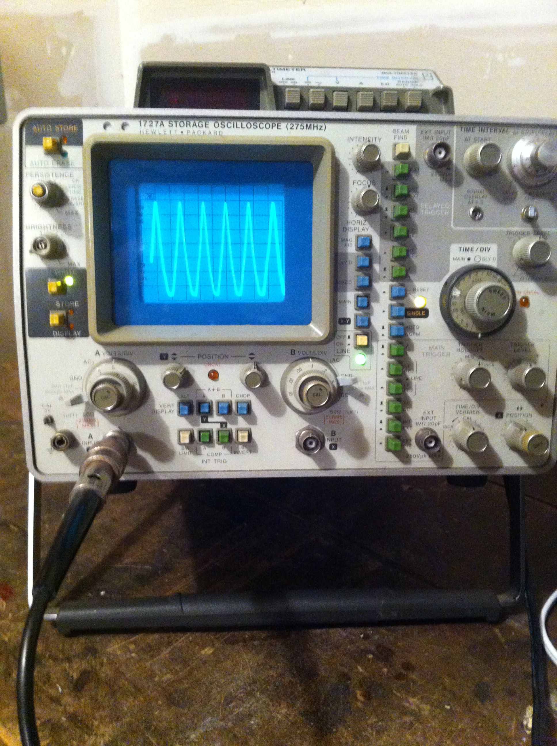
The final pic at the bottom is an oscilloscope trace of the output showing “full wave” rectification. Zero volts is at the top of the screen, meaning the wave is entirely negative volts DC. It is not showing the full power output but a lower voltage representative wave because I don’t have an appropriate probe for my scope to measure more than 200 volts input. Note that because this is a wave, the voltmeter pic at the top of this posting is what is called a “root-mean-square” of the wave, the actual peak voltage at full power is closer to 11,000 volts!
Also of note, the wave is DC, that is, it does not reverse direction though there is an amazing amount of ripple. This could be smoothed out with a giant capacitor but I’m hoping I won’t need one, at least for this stage of the project.
Posted in Nuclear Fusion Reactor by Mark with comments disabled.
Reactor parts arriving…
 Parts…
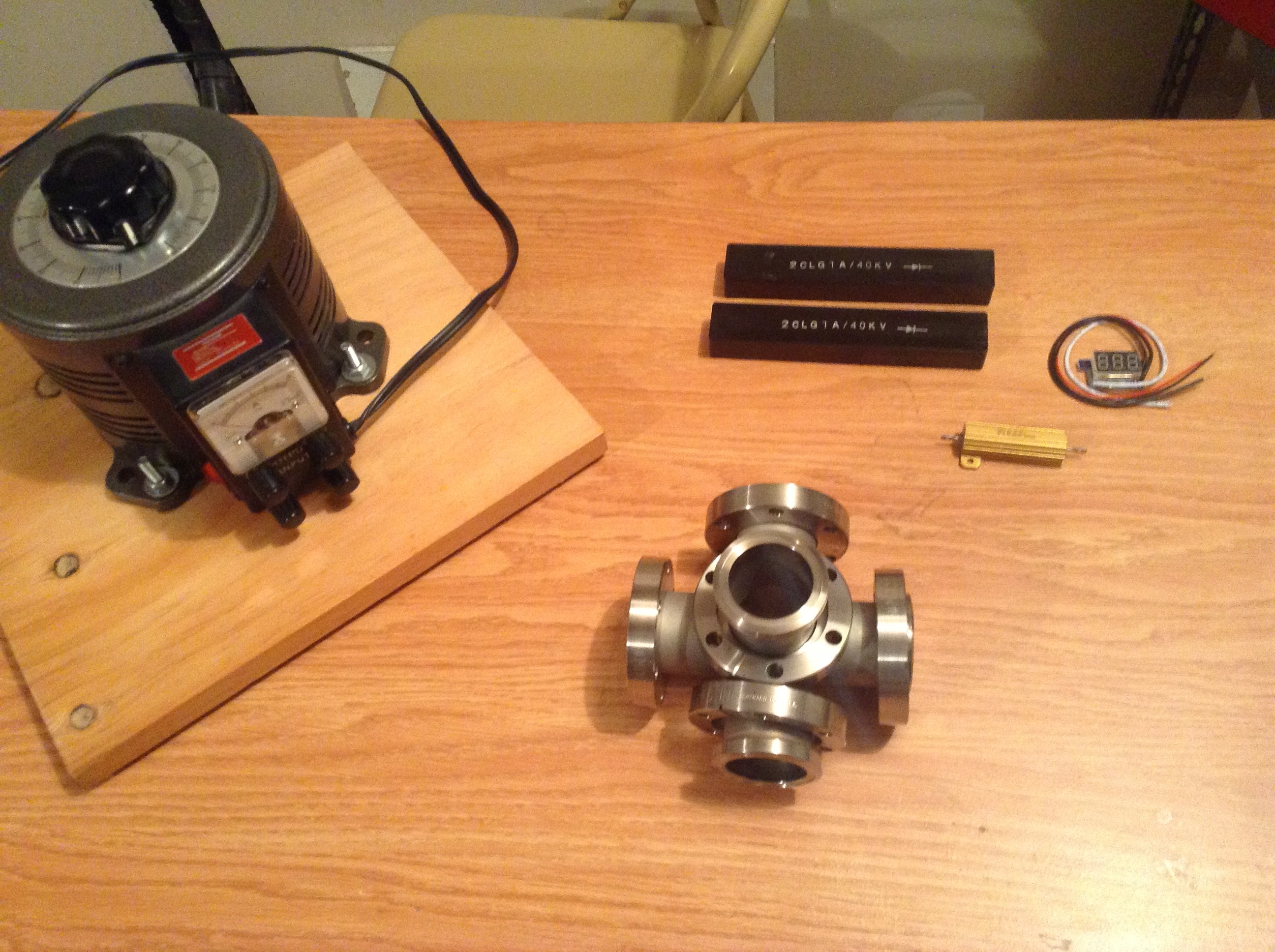
I haven’t had much time to write anything in a while but decided to post an update to my nuclear reactor project. A bunch of parts arrived today, pictured above. Most of what is pictured are components of the power supply, plus one item for the vacuum chamber. The gray cylinder in the upper left with an attached power cord is a variable transformer, used to control the level of the high voltage supply. The two black bars at the top are special high voltage diodes needed to rectify the AC voltage, essentially turning AC into DC. The two small items in the upper left of the pic are components of the current monitoring system, a current meter and a high wattage current shunt.
I’m still waiting for other components of the power supply, namely a high voltage transformer that is capable of converting the 120v AC from a wall outlet into many thousands of volts required for the reactor. I have to build the supply from components, mainly because commercial power supplies, even used ones, usually cost thousands of dollars unless you wait a long time and get lucky on eBay.
The thing in the lower center that looks like a pipe cross is exactly that! It is a 5-way cross that I intend to use as my reactor chamber. It is made of stainless steel and has special connectors at each opening called Conflat flanges. These connectors allow you to attach a vacuum pump, instruments, windows, more pipes, etc., to build a custom ultrahigh vacuum system. Kind of like Legos. Very expensive Legos. A new 5-way cross of this size can run in excess of $600. Much cheaper on eBay.
I also bought a Soviet made neutron counter tube that was shipped from the Ukraine (pic below). I intend to use this as the detector part of the neutron detector. I have no idea if it is still a viable tube, but I’ll try it. Notice that it came packed in newspaper from the Ukraine!
More to come…
Posted in Nuclear Fusion Reactor by Mark with comments disabled.
Geiger counter update!
working!
Damn there is a lot of radiation here in Colorado! My Geiger counter tells me so. And it doesn’t lie.
Amazing little thing, this is. The Geiger-Muller tube, the thing that detects “some” radiation, requires 400 volts to operate. My counter uses two AAA batteries totaling about 3.1 volts. The miracle of electronics I guess…
BTW, did you know that smoke detectors contain the highly radioactive element Americium-241? A very tiny amount that is not harmful, but whose radiation is most definitely detectible. I won’t go into the details, but the radiation is a necessary component of detecting smoke. Americium is a synthetic element, meaning that it doesn’t occur in nature but is man-made. It was discovered, or rather made, during the Manhattan project experiments and is now in almost every building in the country. That may sound trivial, but think about this. It is an atom that was made by humans and does not exist anywhere else in the universe.
Also, it turns out that lantern mantels are made of Thorium, a naturally occurring radioactive element. Again, not harmful in the small amounts used in the mantles. But interestingly, it is used in lanterns because it does not follow black-body radiation characteristics. HUH?!? you might say… What that means is this: As you head a material it starts to emit radiation in the form of photons. Think about an electric stove burner. Notice how intensely hot the element becomes before it starts to glow red. That’s a lot of energy to make an tiny bit of light. To get your oven to produce the brightness of a lantern you would melt the stove and burn your house down. Most substances fall into this category, you’d have to use an exorbitant about of energy to make useable light. But it turns out you can carry a lantern around without burning yourself. That is because Thorium is one of those rare substances that does not follow a black-body radiation curve and glows brightly without producing, or requiring, much heat. Thus it is a great material for lanterns. And it turns out coincidentally, is radioactive!
Ok, enough of that. The next piece of equipment I need for my nuclear reactor is a high voltage power supply, much higher than what comes out of a plug in the house which is about 120 volts. Something with tens of thousands of volts! Lightning generators! Ebay?
Posted in Nuclear Fusion Reactor by Mark with comments disabled.
Outfitting a Nuclear Physics Lab
Geiger Counter Kit
Ok, it turns out that to build a nuclear fusion reactor you basically need to start with a nuclear physics lab. Since I don’t have access to one, I decided to outfit my own lab in my garage. The first order of business was to acquire a Geiger Counter, an instrument to measure radiation. I looked around on eBay and found that professional-looking Geiger Counters cost $400 and up, a bit steep. This is just one of the instruments I need and am on a budget, so instead I found a build-it-yourself kit. For $136.46 (including shipping), I can build my own Geiger Counter, saving at least $300.
A Geiger Counter is necessary for safety, to know if you are pushing into harmful radiation limits. Unfortunately this counter is not calibrated, doesn’t have a meter and the electronics would probably be destroyed if exposed to “a lot” of radiation, whatever that amount is.
But what the hell, it probably works, lol!
Posted in Nuclear Fusion Reactor by Mark with comments disabled.